Magnetic suspension linear guide rail with differential-type serial magnetic circuit structure

A technology of series magnetic circuits and linear guide rails, which is applied in the direction of electric power rails, electric vehicles, magnetic attraction or thrust holding devices, etc., can solve the problems of large volume and weight, large ampere-turns of electric excitation, etc., and achieve small size, Low loss and temperature rise, simple control effect

Inactive Publication Date: 2011-02-16
HARBIN INST OF TECH
View PDF5 Cites 3 Cited by
  • Summary
  • Abstract
  • Description
  • Claims
  • Application Information

AI Technical Summary

Problems solved by technology

[0005] The purpose of the present invention is to solve the problem of large volume and weight of the existing magnetic levitation linear guide due to t

Method used


Image

  • Magnetic suspension linear guide rail with differential-type serial magnetic circuit structure
  • Magnetic suspension linear guide rail with differential-type serial magnetic circuit structure
  • Magnetic suspension linear guide rail with differential-type serial magnetic circuit structure

Examples


specific Embodiment approach 1

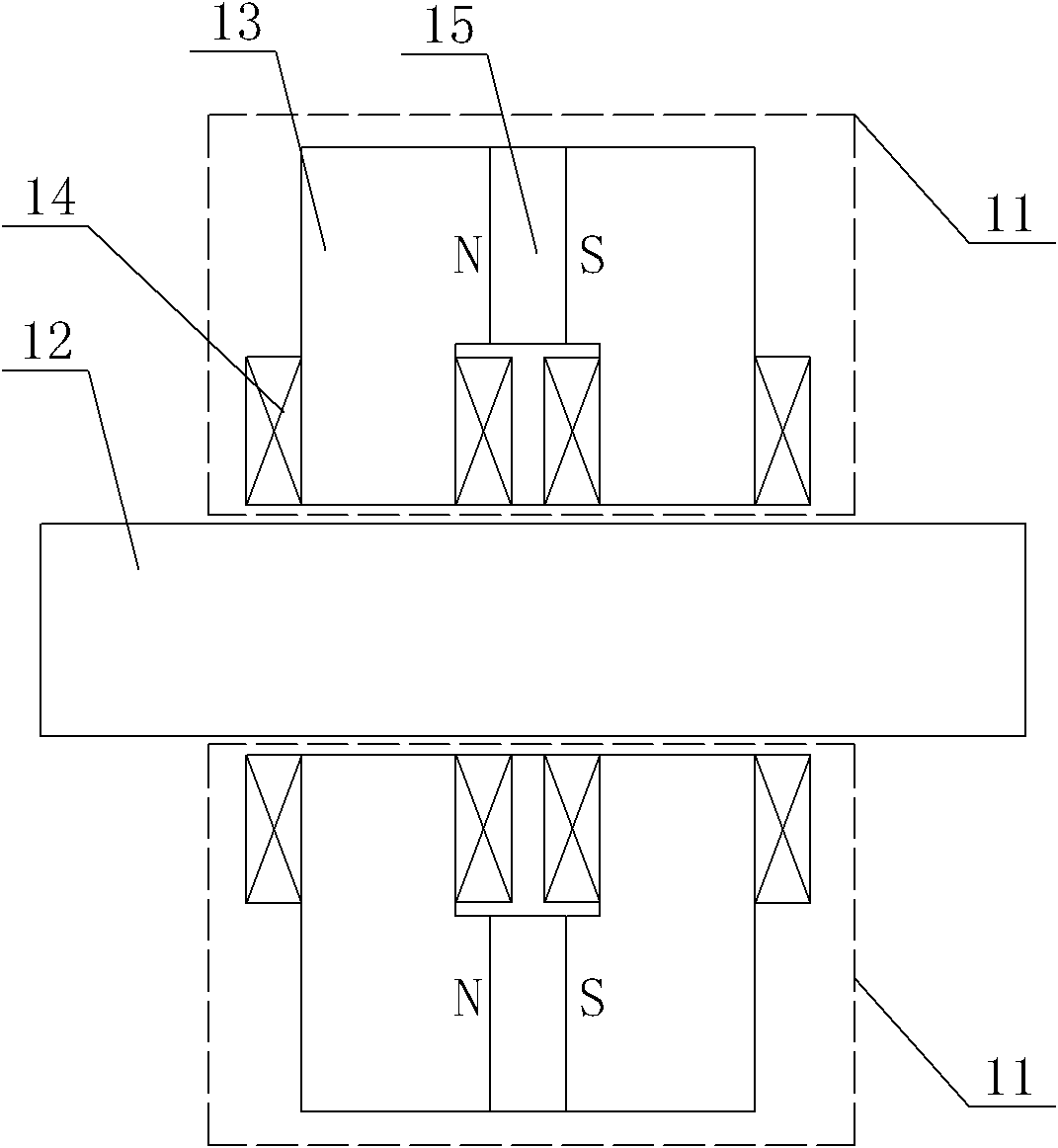
[0030] Specific implementation mode one: the following combination Figures 1 to 4 Describe this embodiment, the differential series magnetic circuit structure magnetic levitation linear guide described in this embodiment is composed of a primary and a secondary, the primary is composed of two primary units 11, and the two primary units 11 are symmetrically arranged on the the upper and lower sides of the secondary;

[0031] The primary unit 11 is composed of a gate-shaped primary core 13, two control coils 14 and a strip-shaped permanent magnet 15,

[0032] The opening side of the gate-shaped primary iron core 13 is opposite to the secondary, and a control coil 14 is respectively wound on the two vertical sections of the gate-shaped primary iron core 13,

[0033] The gate-shaped primary iron core 13 is a symmetrical segmented structure, and the strip-shaped permanent magnet 15 is clamped between each segment of the gate-shaped primary iron core 13, and the connecting end fac...

specific Embodiment approach 2

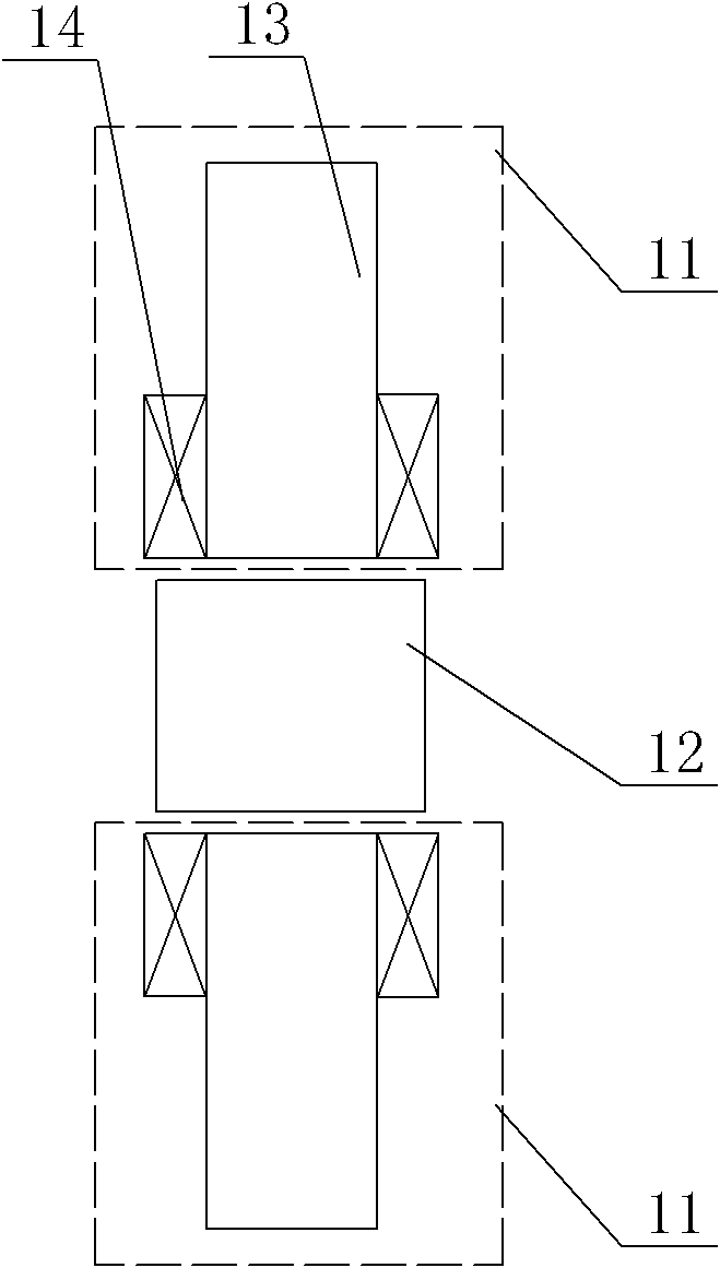
[0038] Specific implementation mode two: the following combination figure 1 with figure 2 Describe this embodiment. This embodiment is a further description of Embodiment 1. The gate-shaped primary iron core 13 is a two-stage structure, each iron core is L-shaped, and the elongated permanent magnet 15 is clamped between the two L-shaped Between the iron cores, the elongated permanent magnets 15 are magnetized in parallel along the horizontal direction. Other components and connections are the same as those in Embodiment 1.

specific Embodiment approach 3

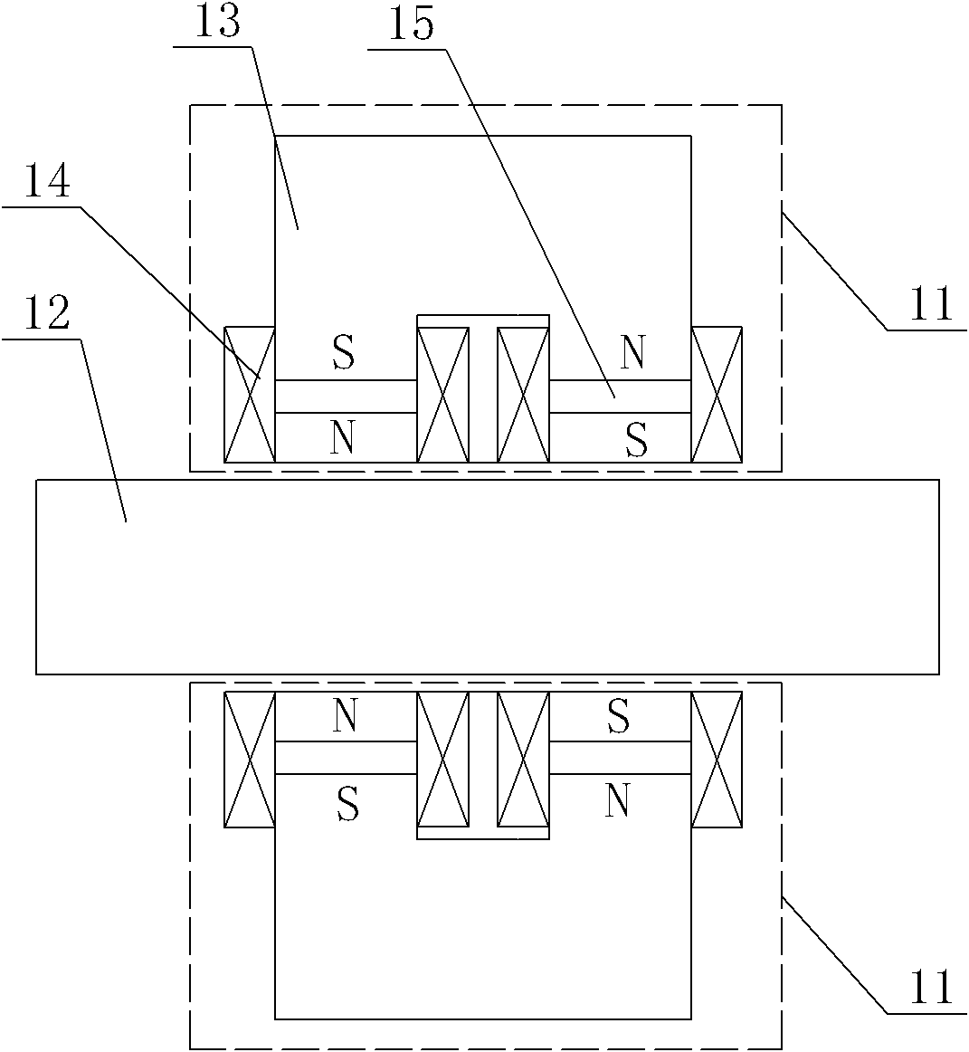
[0039] Specific implementation mode three: the following combination image 3 with Figure 4 Describe this embodiment, this embodiment is a further description of Embodiment 1: the gate-shaped primary iron core 13 is a three-section structure, and each vertical section wrapped around the control coil 14 is composed of two sections, and the two-section iron core A strip-shaped permanent magnet 15 is clamped therebetween, and the position of the strip-shaped permanent magnet 15 corresponds to the middle section of the wound control coil 14;

[0040] Each strip-shaped permanent magnet 15 is magnetized in parallel along the vertical direction, and the magnetization directions of the two strip-shaped permanent magnets 15 located on the same gate-shaped primary core 13 are opposite. Other components and connections are the same as those in Embodiment 1.


PUM


Abstract

The invention discloses a magnetic suspension linear guide rail with a differential-type serial magnetic circuit structure, belonging to the technical field of motors. The invention solves the problems of large volume and large weight caused by large ampere turns of electrical excitation of the traditional magnetic suspension linear guide rail. Based on one technical scheme, two primary units are symmetrically arranged at the upper side and the lower side of a secondary unit; the opening side of a door-shaped primary iron core is relative to the secondary unit, a control coil is respectively wound on two vertical segmentations of the door-shaped primary iron core, a long strip permanent magnet is clamped and fixed between every two segmentations of the door-shape primary iron core, the jointed end surface of an elongated permanent magnet and the segmented iron core is the same as the end surface shape of the corresponding segmented iron core, all control coils are connected in series, and the secondary unit comprises a magnetic conductive yoke. Based on the other technical scheme, the magnetic conductive yoke is in an integrated structure or a two-segmentation structure, and the elongated permanent magnet is arranged on the surface of the magnetic conductive yoke in the integrated structure or is embedded between two segmentations of the magnetic conductive yoke in the two-segmentation structure. The invention is suitable for being used in the magnetic suspension linear guide rail.

Description

technical field [0001] The invention relates to a differential series magnetic circuit structure magnetic levitation linear guide rail, which belongs to the technical field of motors. Background technique [0002] At present, the support methods of linear motion bodies mainly include linear sliding bearings, linear rolling bearings, linear guide rails and linear air bearings, among which linear sliding bearings and linear rolling bearings are only suitable for supporting short-stroke moving bodies; Rail, linear motion guide rail, linear slide rail or linear rolling guide rail, it has the advantages of high positioning accuracy, strong bearing capacity, small wear, adaptable to high-speed motion, unlimited travel, easy assembly and interchangeability, etc., has become a variety of Indispensable and important functional components in machine tools, CNC machining centers, and precision electronic machinery; linear air bearing guides have the advantages of high speed, high preci...

Claims


Application Information

Patent Timeline
IPC IPC(8): B60M1/30H02N15/00B60L13/04
Inventor 寇宝泉张赫张鲁
Owner HARBIN INST OF TECH
Why Eureka
Try Eureka