
Fan integral installation rotating holding mechanism

An overall installation and fan technology, applied in the direction of wind power engine, machine/engine, wind power motor transportation, etc., can solve problems such as waste, time-consuming and labor-intensive, and environmental pollution

Inactive Publication Date: 2011-02-16
SANY ELECTRIC CO LTD
View PDF4 Cites 27 Cited by
  • Summary
  • Abstract
  • Description
  • Claims
  • Application Information

AI Technical Summary

Problems solved by technology

This kind of installation and construction is not only time-consuming and laborious, but also because the lifting flange is welded on the tower tube, the tower tube is prone to brittle cracks, and the weld seam is easy to corrode, which affects the mechanical properties of the tower tube
In addition, because the lifting flange cannot be reused, waste is generated, and it is easy to damage and pollute the environment
[0011] With the continuous enlargement and offshore of wind turbines, the limitation of lifting capacity and lifting height and the complexity of sea conditions make the traditional hoisting form useless

Method used


Image

  • Fan integral installation rotating holding mechanism
  • Fan integral installation rotating holding mechanism
  • Fan integral installation rotating holding mechanism

Examples


Embodiment Construction

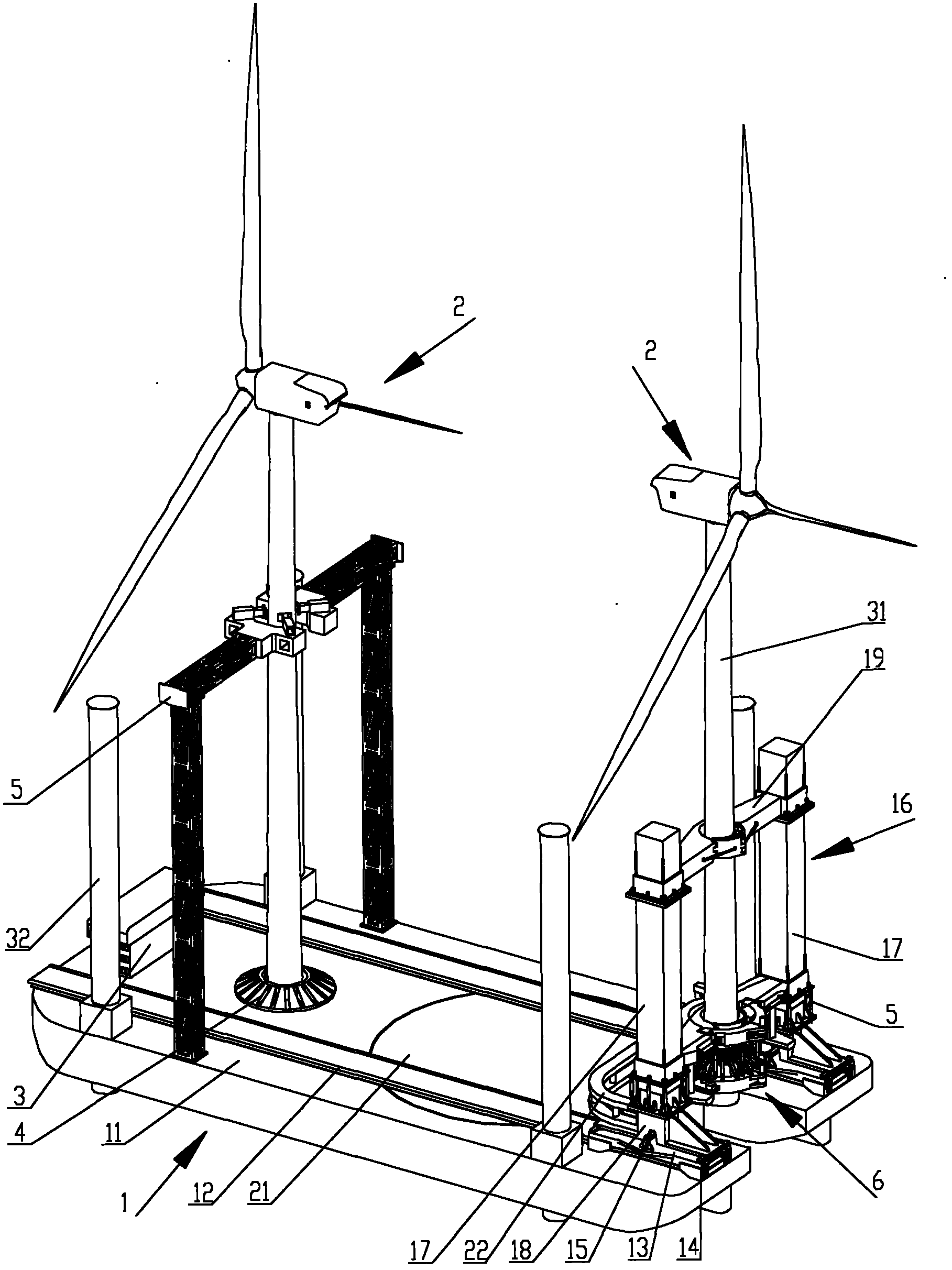
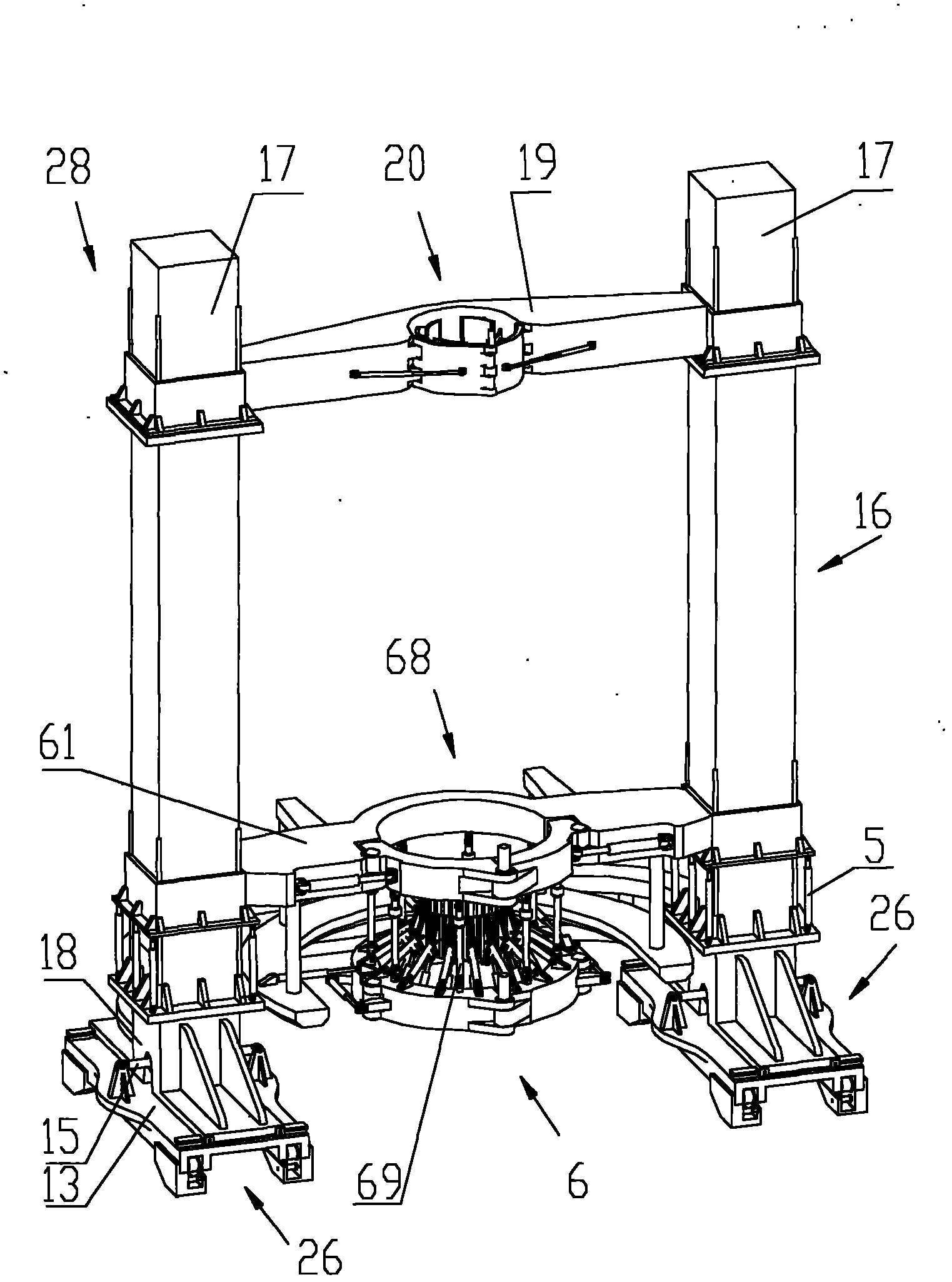
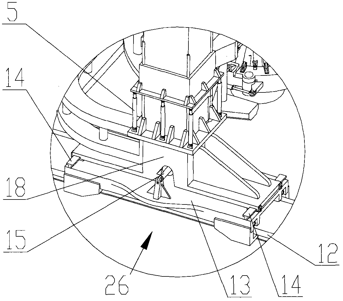
[0034] figure 1 It is a three-dimensional view of the transportation and installation platform 1 for the integration of fan transportation and installation, figure 2It is a perspective view of the holding frame 28 when the fan is not held, image 3 It is a partially enlarged perspective view of the base portion 18 of the lifting frame 28 . Such as figure 1 As shown, in the roughly four corners of the fan transportation and installation platform 1, there are four legs 32, and a driver's cab 3 is arranged in the front, and on the deck behind the driver's cab 3, a fixed pedestal 4 and a fixed frame for fixing the fan 2 are provided. Frame 5 (when it is designed only for fan installation, no fixed base and fixed frame are provided). At the rear of the middle part of the fan transportation and installation platform 1 (the bow side is called the front, the stern side is called the rear, the same below), there is a lifting and turning platform 21, and at the longitudinal rear end...


PUM


Abstract

The invention discloses a fan integral installation rotating holding mechanism which is used for a sea fan installing platform and comprises a bearing beam, a plurality of suspenders, a cradle, a plurality of holding device, a torsion device, a transverse vernier device and a longitudinal vernier device, wherein the bearing beam is arranged between two upright posts of a portal frame, provided with a center circular ring in the middle and can move up and down along the two upright posts; the suspenders are arranged at the lower end of the center circular ring; the cradle is suspended at the lower end of the center circular ring through the suspenders; the holding devices are distributed on the cradle along the circumferential direction; and the torsion device, the transverse vernier device and the longitudinal vernier device are arranged between the cradle and a connecting frame and used for driving the cradle to rotate or horizontally move. The invention can conveniently realize the alignment of a tower cylinder center and a connecting flange bolt hole under the state of holding a tower cylinder below a fan; after the installation and the construction are finished, the rotating holding mechanism is opened, the fan can be separated, and the installing platform can drive away from the fan.

Description

technical field [0001] The invention relates to the technical field of marine engineering equipment, in particular to a rotating holding and lifting mechanism for integral installation of offshore wind power generating sets. Background technique [0002] Wind energy is a clean energy. Wind power generation is a power generation method that converts the kinetic energy of the wind into mechanical energy, and then converts the mechanical energy into electrical energy. Since the development of wind farms on land has been basically completed, and the wind resources at sea are very rich, more and more wind farms are built at sea. The installation of wind turbines (that is, wind turbines) is a crucial step in the construction of wind farms at sea. Installing the wind turbine refers to installing the wind turbine on the installation base (usually a connecting flange) on the foundation of the wind turbine set in the sea in advance. Generally, it needs to be installed with the help...

Claims


Application Information

Patent Timeline
IPC IPC(8): B66F11/00
CPCF03D1/005F05B2240/95B66C1/108Y02E10/72F03D13/40Y02E10/727
Inventor 任明琪王雷
Owner SANY ELECTRIC CO LTD
Learn More