
Motorcycle steering lamp

A technology for turn signals and motorcycles, applied to lampshades, lighting and heating equipment, lighting devices, etc., can solve problems such as glare, hidden safety hazards, and poor visual effects, and achieve beautiful appearance, soft light, and good visual effects

Inactive Publication Date: 2011-02-16
力帆科技(集团)股份有限公司
View PDF4 Cites 1 Cited by
  • Summary
  • Abstract
  • Description
  • Claims
  • Application Information

AI Technical Summary

Problems solved by technology

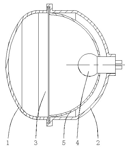
In the process of use, we found that the light intensity after being concentrated by the lamp bowl 5 is too strong, which directly causes the light intensity of the turn signal to be too strong. At the same time, there is a bright spot in the center of the light, which is very dazzling and will not only affect pedestrians In addition, the image seen by pedestrians is mainly a group of bright light spots, and the general outline and shape of the turn signal cannot be seen clearly. question

Method used


Image

  • Motorcycle steering lamp
  • Motorcycle steering lamp
  • Motorcycle steering lamp

Examples


Embodiment 1

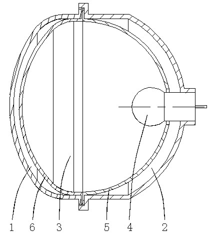
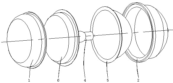
[0017] Such as figure 2 , 3 As shown, a motorcycle turn signal is composed of a transparent lampshade 1, a mounting base 2, a light bulb 4, a lamp bowl 5 and a diffuse reflective lampshade 6, wherein the transparent lampshade 1 is connected to the edge of the mounting base 2 to form a closed inner Cavity 3. The connection method between the transparent lampshade 1 and the installation base 2 can be bolted connection, fastening method, or bonding method. The light bulb 4 and the lamp bowl 5 are arranged in the inner cavity 3, wherein the edge of the lamp bowl 5 is bent outward to form a flanging (not shown in the figure), and the edge of the flanging is stuck between the transparent lampshade 1 and the installation base 2's butt joint. The lamp holder of the light bulb 4 passes through the through hole in the center of the lamp bowl 5 and is fixed in the through hole on the installation base 2, and the end of the lamp holder of the light bulb 4 is exposed outside the instal...

Embodiment 2

[0020] Such as Figure 4 , 5 As mentioned above, in this embodiment, the diffuse reflective lampshade 6 is composed of a cover body 6a and an outer flange 6b arranged on the edge of the cover body. When the diffuse reflective lampshade 6 is docked with the lamp bowl 5, the The edge of the flange 6b is clamped at the junction of the transparent lampshade 1 and the mounting base 2, and the shade 6a is in the shape of a five-pointed star. In addition, the diffuse reflective lampshade 6 can also be shaped according to the specific shapes of the transparent lampshade 1, the mounting base 2 and the lamp bowl 5, so that the diffusely reflective lampshade 6 can present other shapes. The same, and will not be repeated here.


PUM


Abstract

The invention discloses a motorcycle steering lamp. The motorcycle steering lamp comprises a transparent lampshade and a mounting base, wherein the transparent lampshade is butted with the mounting base to form a cavity; the inside of the cavity is provided with a lamp bulb and a lamp bowl; the edge of the lamp bowl is clamped in the butting part of the transparent lampshade and the mounting base; the lamp holder of the lamp bulb penetrates through a through hole at the center of the lamp bowl to be fixed on the mounting base; the inside of cavity is provided with a diffuse reflection diffuser, the diffuse reflection diffuser is butted with the lamp bowl, and the inner or outer surface of the diffuse reflection diffuser is a rough surface. The diffuse reflection diffuser is added on the motorcycle steering lamp to adjust the light concentrated by the lamp bowl, thus the light Intensity can be reduced appropriately, the light emitted to the outside of the steering lamp becomes softer and more uniform and can not form light spots at the center, the visual angle of pedestrians can not be affected, the main outline of the steering lamp can be seem by the pedestrians; and the motorcycle steering lamp has good visual effect and beautiful appearance.

Description

technical field [0001] The invention belongs to a motorcycle component, in particular to a motorcycle steering lamp. Background technique [0002] Such as figure 1 As shown, the traditional motorcycle turn signal includes a transparent lampshade 1 and a mounting base 2, the two are docked to form an inner cavity 3, and a light bulb 4 and a lamp bowl 5 are installed in the inner cavity 3, wherein the edge of the lamp bowl 5 is stuck on the transparent At the joint between the lampshade 1 and the installation base 2 , the lamp socket of the bulb 4 passes through the through hole in the center of the lamp bowl 5 and is fixed on the installation base 1 . The light bulb 4 emits light after being energized, the light emitted by the light bulb 4 becomes stronger after being concentrated by the lamp bowl 5, and the concentrated light is reflected to the transparent lampshade 1 through the lamp bowl 5 at the same time, and then refracted out through the transparent lampshade 1 to ac...

Claims


Application Information

Patent Timeline
IPC IPC(8): F21V3/04F21S8/10F21V17/10F21V7/22F21W101/12
Inventor 邓小毛何长渝刘彬
Owner 力帆科技(集团)股份有限公司
Learn More