Optical detection method for parallelism of planar array CCD target surface and installation locating surface

An optical detection and mounting surface technology, applied in the direction of optical devices, measuring devices, mechanical gap measurement, etc., can solve problems affecting CCD imaging quality, difficult optical system focal depth requirements, poor parallelism of CCD target surface, etc., to achieve Reliable measurement method, improved image quality, and easy operation

Inactive Publication Date: 2012-02-08
CHANGCHUN INST OF OPTICS FINE MECHANICS & PHYSICS CHINESE ACAD OF SCI
View PDF3 Cites 2 Cited by
  • Summary
  • Abstract
  • Description
  • Claims
  • Application Information

AI Technical Summary

Problems solved by technology

[0004] The present invention solves the problem that the parallelism between the existing CCD mechanical installation positioning surface and the CCD target surface is poor, and it is difficult to achieve the focal depth requirement of the optical system, thereby affecting the CCD imaging quality.

Method used


Image

  • Optical detection method for parallelism of planar array CCD target surface and installation locating surface
  • Optical detection method for parallelism of planar array CCD target surface and installation locating surface
  • Optical detection method for parallelism of planar array CCD target surface and installation locating surface

Examples


specific Embodiment approach 1

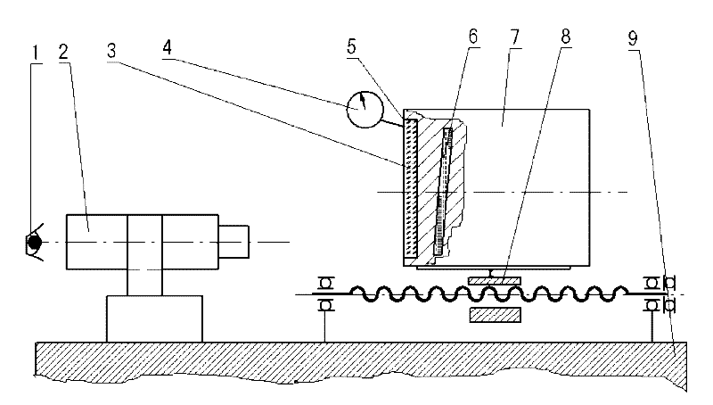
[0017] Specific implementation mode 1. Combination figure 1 and figure 2 Illustrate this embodiment, a kind of optical detection method of the parallelism between the target surface 6 of the area array CCD and the installation positioning surface, the method is completed by the following steps:

[0018] Step 1, using a high-precision linear displacement platform 8 to move the CCD target surface 6 and the mechanical installation surface 5 to the focal plane of the tool microscope 2 respectively;

[0019] Step 2, using the dial indicator 4 to measure the moving distance of the high-precision linear displacement platform 8, and using the moving distance of the high-precision linear displacement platform 8 as the distance between the CCD target surface 6 and the mechanical installation surface 5;

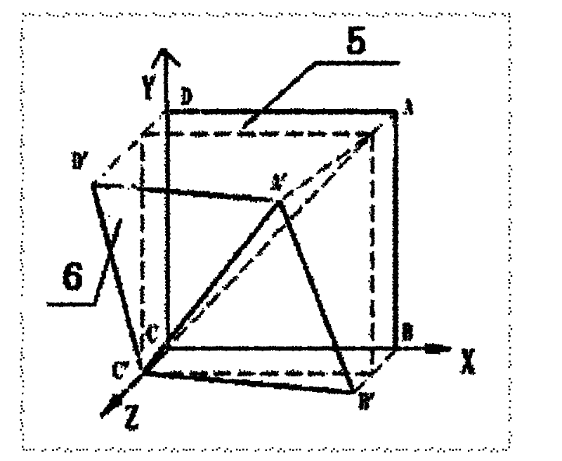
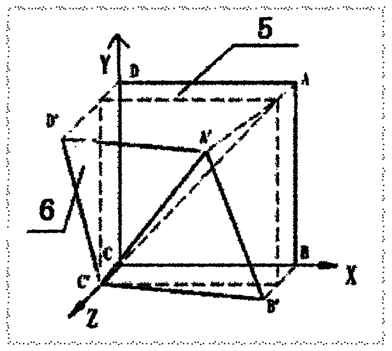
[0020] Step 3: Use any right-angled vertex of the CCD target surface 6 as the origin of the Cartesian coordinate system, and the corresponding two right-angled sides as the X-axis and...

specific Embodiment approach 2

[0023] Specific embodiment two, combine figure 2 Describe this embodiment, this embodiment is the specific example of the optical detection method of the parallelism of a kind of area array CCD target surface 6 described in the specific embodiment 1 and the installation positioning surface:

[0024] The measuring tool of the present embodiment is: tool microscope 2, dial indicator 4, high-precision linear displacement platform 8; the displacement resolution of the high-precision linear displacement platform 8 is 0.005; the measuring tool is placed on the marble platform 9, A CCD protective glass 3 is arranged in front of the rectangular area array CCD target surface 6, and a non-contact optical measurement method is adopted to observe the value read by the tool microscope 2 through the human eye 1 and calculate the distance between the CCD target surface 6 and the mechanical installation surface 5 on the X axis, The angle between the Y axis and the diagonal direction, and the...


PUM


Abstract

The invention discloses an optical detection method for parallelism of a planar array CCD target surface and a mounting locating surface, which relates to an optical detection method for parallelism of a CCD target surface and a mechanical mounting surface. The invention solves the problems of poor parallelism of the prior CCD mechanical mounting locating surface and CCD target surface and difficulty in realizing focal depth of the optical system, thereby influencing the CCD imaging quality. The method comprises the following steps: setting any right-angle vertex of the rectangular CCD targetsurface as the initial point of a rectangular coordinate system, and setting the corresponding two right-angle sides respectively as X-axis and Y-axis; and respectively reading the distance values between four vertices of the CCD target surface and the corresponding mechanical mounting surface by using a tool microscope, calculating the differences delta h between three of the four values and theinitial point value, and respectively dividing by the side lengths in the X and Y directions and the distance l in the diagonal line direction, thereby respectively obtaining the included angles between the CCD target surface and the mounting locating surface in the X and Y directions and the diagonal line direction. The invention has the advantages of simple principle, high precision and easy realization.

Description

technical field [0001] The invention relates to an optical detection method for the parallelism between an area array CCD target surface and an installation positioning surface. Background technique [0002] After the area array CCD target surface is packaged in the housing, its installation positioning surface and the CCD target surface should be strictly parallel. This parallelism should meet the requirements of the focal depth of the optical system That is, the depth of focus Δδ is equal to the square of the numerical aperture of the 4-times wavelength optical system. For an optical system with a numerical aperture of less than 2 in the visible light band, the depth of focus is less than 0.01mm. At present, the parallelism between most of the CCD installation positioning surface and the CCD target surface can meet the requirement of this depth of focus Δδ. For some newly developed CCDs, due to various reasons, their parallelism cannot meet the requirement of this foca...

Claims


Application Information

Patent Timeline
Patent Type & Authority Patents(China)
IPC IPC(8): G01B11/26G01B5/14
Inventor 王志王志臣王建立赵勇志张艳辉
Owner CHANGCHUN INST OF OPTICS FINE MECHANICS & PHYSICS CHINESE ACAD OF SCI
Why Eureka
Try Eureka