Method and system for circularly charging and discharging energy storage component

An energy storage component, charging and discharging technology, applied in the direction of electrical components, battery circuit devices, collectors, etc., can solve the problems of affecting service life, recharging performance, and power generation reduction

Inactive Publication Date: 2011-02-16
叶伟清
View PDF4 Cites 4 Cited by
  • Summary
  • Abstract
  • Description
  • Claims
  • Application Information

AI Technical Summary

Problems solved by technology

When encountering rainy weather, because solar power generation is strongly affected by light radiation, the light intensity in rainy days is generally 1 / 5-1 / 10 of daily, and the power generation is also reduced accordingly. At this time, the accumulated power in a single day may only be 1 / 10 of the usual / 5, far from meeting the lighting needs of the whole night, the system will be in a low-voltage shutdown state, and must rely on an external power supply to work
If the system specifications are increased to withstand rainy weather, then every time a rainy day passes, the corresponding energy storage element capacity and solar panel capacity must be doubled from the base value, that is, the cost is doubled
At the same time, in long-term cloudy and rainy days, it has been a declining process for the power to make ends meet. The long-term work and under-power state of the energy storage components seriously affect the service life and recharging performance.

Method used


Image

  • Method and system for circularly charging and discharging energy storage component
  • Method and system for circularly charging and discharging energy storage component
  • Method and system for circularly charging and discharging energy storage component

Examples


Embodiment Construction

[0016] Preferred embodiments of the present invention will be described in detail below in conjunction with the accompanying drawings.

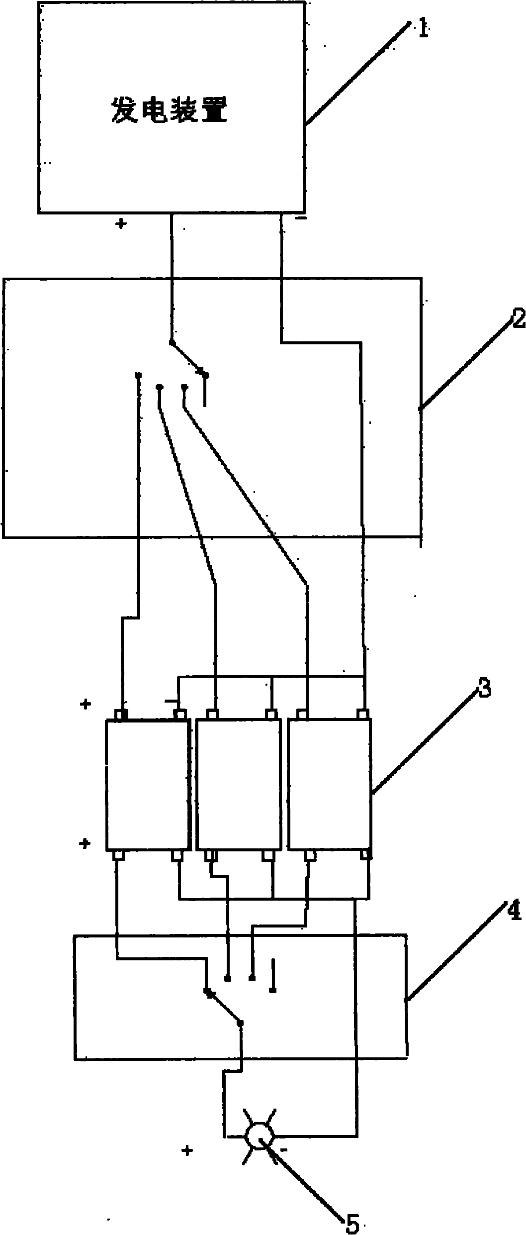
[0017] Such as figure 1 As shown, the energy storage element cycle charging and discharging system includes a power generation device 1, the power generation device 1 is connected to an energy storage element through a first control unit 2, the energy storage element is divided into several energy storage units 3, and the first control unit 2 can The control generator 1 is connected to several energy storage units 3 in one-to-one correspondence, the energy storage element is connected to the load 5 through the second control unit 4 , and the second control unit 4 can control the load 5 to be connected to the several energy storage units 3 in one-to-one correspondence. The power generating device can be a solar panel, a fan or other green energy generating devices.

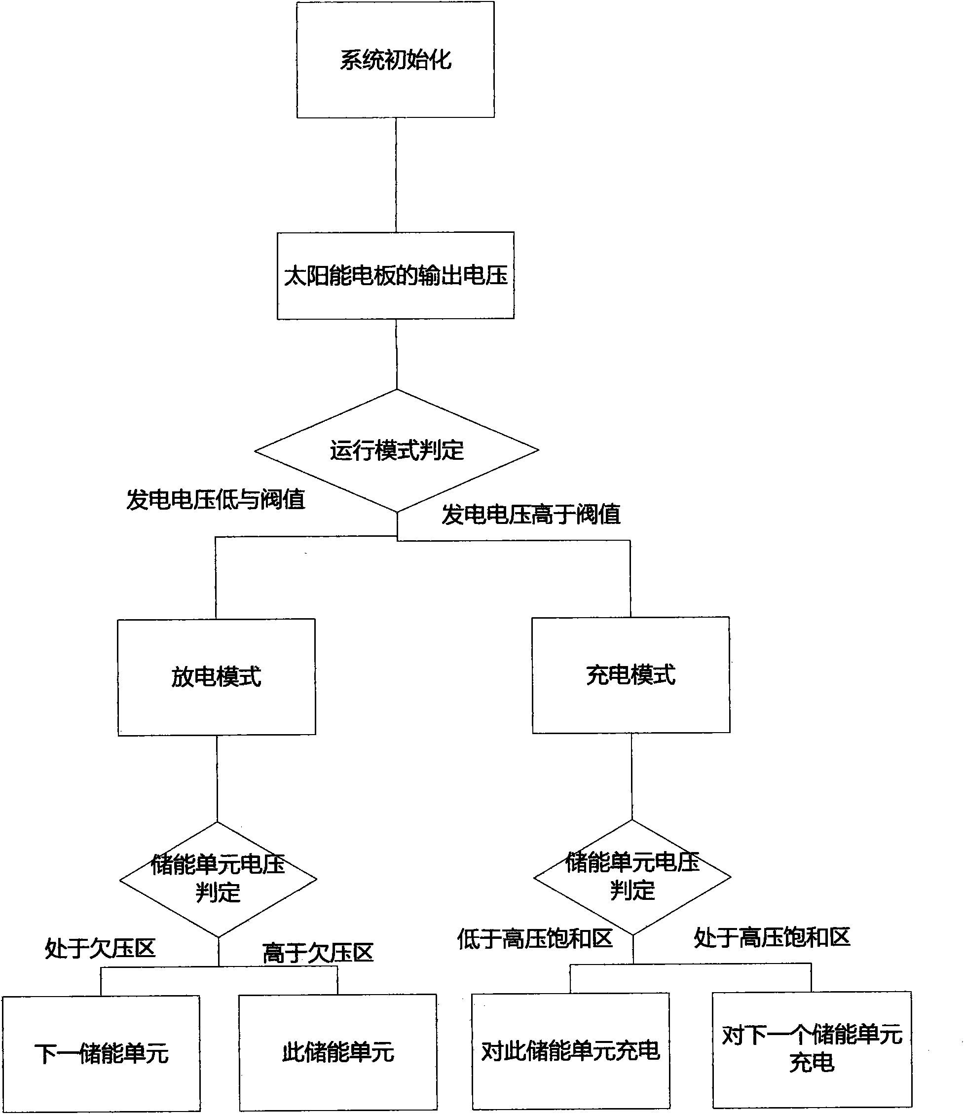
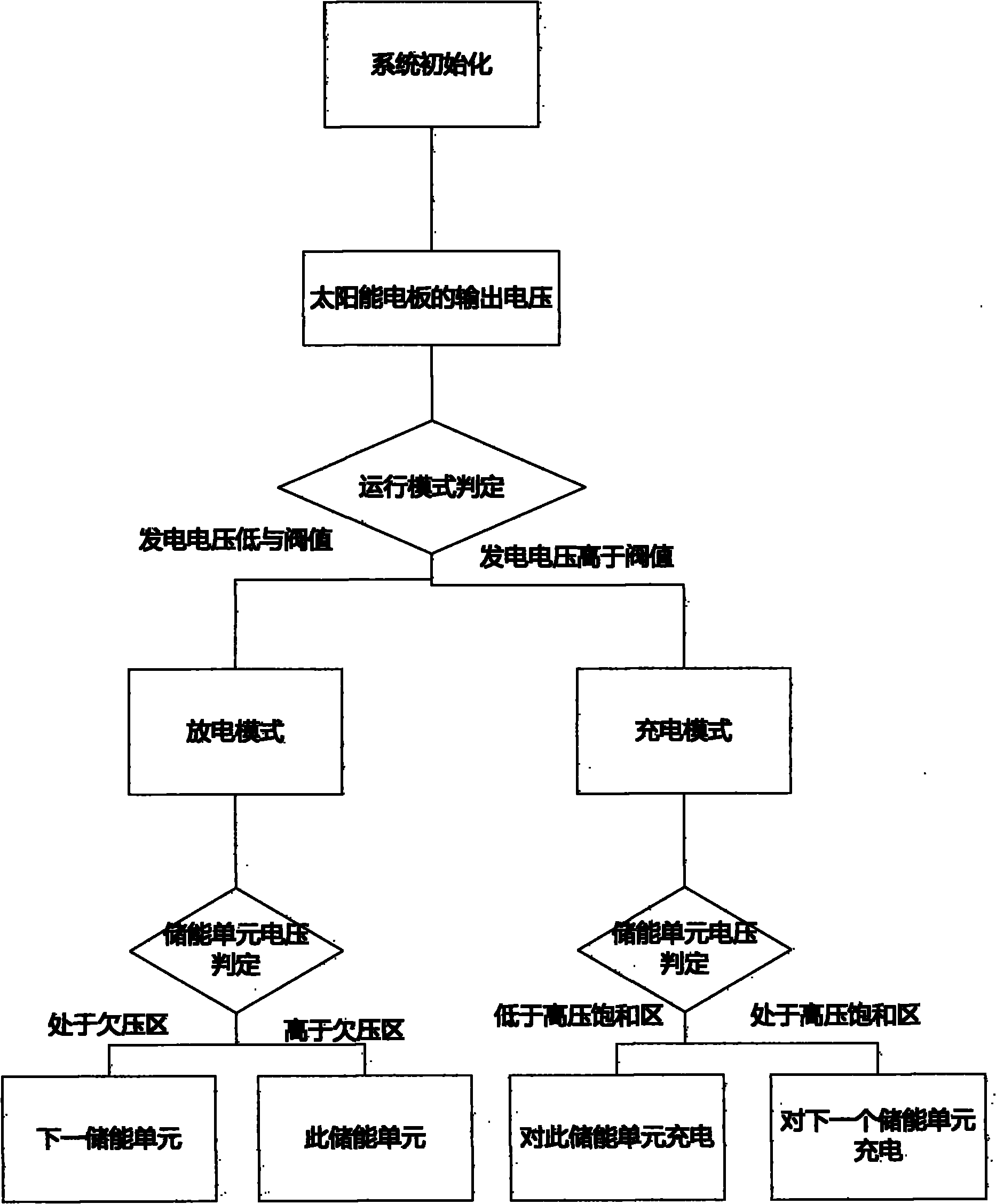
[0018] Taking the power generation device as a solar panel as an example, th...


PUM


Abstract

The invention discloses a method and a system for circularly charging and discharging an energy storage component. The system comprises an energy storage component and a power generating device. The method comprises the following steps of: dividing the energy storage component into a plurality of energy storage units; during discharge, discharging one energy storage unit at first, and then discharge next energy storage unit when the voltage of the previous energy storage unit is dropped to an undervoltage region from high pressure saturation region; and during charge, charging one energy storage unit by the power generating device at first, and switching to charge the next energy storage unit when the voltage of the previous energy storage unit is increased from the undervoltage region to the high pressure saturation region. The method can be used for effectively prolonging the service life of the energy storage component.

Description

technical field [0001] The invention relates to a charging and discharging method for an energy storage device, in particular to a charging and discharging method for an energy storage device charged by solar or wind energy devices. Background technique [0002] In the traditional integrated off-grid photovoltaic system, the power generated by off-grid green power generation devices such as solar panels or fans has uncertain factors such as uneven time distribution, and an intermediate storage device is required to collect scattered power. , and reunify the supply when needed. However, the biggest problem with this kind of off-grid system is that all kinds of green energy power generation devices are not in constant supply. When the fluctuation range reaches a certain level, the energy in the energy storage equipment is exhausted and cannot be replenished, and there may be an energy gap, which makes The energy storage device cannot be fully charged for a long time, or even ...

Claims


Application Information

Patent Timeline
Patent Type & Authority Applications(China)
IPC IPC(8): H02J7/00
Inventor 叶伟清付晶
Owner 叶伟清
Why Eureka
Try Eureka