Variable-pitch servo driver with function of energy storage

A servo driver and functional technology, which is applied in the output power conversion device, the conversion of AC power input to AC power output, and the control of AC motor, etc., can solve the problem of undiscovered pitch servo drives, and the overall structure and control of the pitch system are complex. and other problems, to achieve the effect of compact structure, high reliability requirements and cost reduction

Inactive Publication Date: 2011-02-16
SHANGHAI JIAO TONG UNIV +1
View PDF4 Cites 12 Cited by
  • Summary
  • Abstract
  • Description
  • Claims
  • Application Information

AI Technical Summary

Problems solved by technology

As a result, the overall structure and control of the pitch system are complicated
[0004] After searching the existing literature, it is found that the existing technology mainly focuses on the backup power supply of the pitch system, and no related reports on the pitch servo drive with energy storage function have been found so far.

Method used


Image

  • Variable-pitch servo driver with function of energy storage
  • Variable-pitch servo driver with function of energy storage
  • Variable-pitch servo driver with function of energy storage

Examples


Embodiment 1

[0020] This embodiment is a 10kW electric servo pitch driver, the rated torque of the selected motor is 30Nm, and the rated speed is 2200rpm. In emergency feathering, the motor is required to run at a speed of 3000rpm and a torque of 30Nm for 10s. The entire servo driver can be powered off in the power grid Maintain normal operation for 3s.

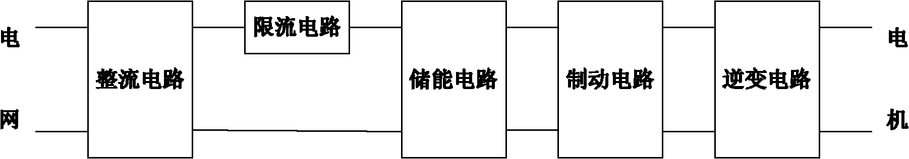
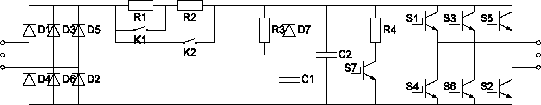
[0021] Such as figure 1 and figure 2 As shown, this embodiment includes: a rectification circuit, a current limiting circuit, an energy storage circuit, a braking circuit and an inverter circuit, wherein: the input terminal of the rectification circuit is connected to the power grid to transmit AC voltage, and an output terminal of the rectification circuit is connected to the current limiting circuit The input terminal of the circuit is connected to transmit DC voltage, the other output terminal of the rectifier circuit is connected to one input terminal of the energy storage circuit to transmit DC voltage, the output terminal of the c...

Embodiment 2

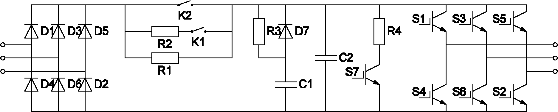
[0040] Such as image 3 As shown, the difference between this embodiment and Embodiment 1 is that: the current limiting circuit includes: a first resistor R1, a second resistor R2, a first contactor K1 and a second contactor K2, wherein: the first resistor R1 One end of the second resistor R2, one end of the second contactor K2 are respectively connected to the positive output end of the rectifier circuit two by two, the other end of the second resistor R2 is connected to one end of the first contactor K1, and the second contactor The other end of K2, the other end of the first contactor K1, the other end of the first resistor R1 and an input end of the energy storage circuit are respectively connected in pairs.

[0041] In this embodiment, the resistance value of the first resistor R1 is 94 ohms, the resistance value of the second resistor R2 is 33 ohms, the rated voltage of the first contactor K1 and the second contactor K2 are both 600VDC, the first contactor K1 and The ra...


PUM


Abstract

The invention discloses a variable-pitch servo driver with a function of energy storage, which belongs to the technical field of wind power generation. The variable-pitch servo driver comprises a rectifying circuit, a current limiting circuit, an energy-storage circuit, a braking circuit and an inverting circuit, wherein the input end of the rectifying circuit is connected with a power grid so asto transmit alternating voltages, one output end of the rectifying circuit is connected with the input end of the current limiting circuit so as to transmit direct voltages, and the other output end of the rectifying circuit is connected with one input end of the energy-storage circuit so as to transmit the direct voltages; and the output end of the current limiting circuit is connected with the other input end of the energy-storage circuit so as to transmit the direct voltages subjected to current limiting, the output end of the energy-storage circuit is connected with the input end of the braking circuit so as to transmit the direct voltages, the output end of the braking circuit is connected with the input end of the inverting circuit so as to transmit the direct voltages, and the output end of the inverting circuit is connected with a driven motor so as to transmit the alternating voltages. The variable-pitch servo driver of the invention is not required to be equipped with other standby powers, is compact in structure, is beneficial to shorten the volume of the whole system, and significantly reduces the cost of a variable-pitch system.

Description

technical field [0001] The invention relates to a device in the technical field of wind power generation, in particular to a pitch servo drive with energy storage function. Background technique [0002] Grid-connected wind turbines continue to develop toward large capacity. At present, the newly installed large-capacity units are basically pitch units. In the pitch unit, the pitch system has two kinds of electric servo pitch and hydraulic pitch. The electric servo pitch actuator uses a motor to individually control the blades, and its structure is compact, reliable, and can independently change the pitch. Judging from the situation at home and abroad, electric servo pitch is gradually replacing hydraulic pitch to become the mainstream of large wind turbine pitch systems. [0003] One of the main differences between the electric servo pitch system and the ordinary servo system is that in order to meet the needs of the electric servo pitch system for feathering in emergency...

Claims


Application Information

Patent Timeline
Patent Type & Authority Applications(China)
IPC IPC(8): H02M5/45H02P27/04H02J9/04
CPCY02B10/70
Inventor 凌志斌蔡旭蔡翔
Owner SHANGHAI JIAO TONG UNIV
Why Eureka
Try Eureka