Large current deexcitation loop based on silicon controlled rectifier subject to multi-redundancy trigger of jumper

A trigger control and jumper technology, which is applied in the direction of controlling generators, control systems, emergency protection circuit devices, etc., can solve the problem of large-capacity generator sets with large demagnetization current, and a single thyristor jumper cannot meet the maximum demagnetization current. De-excitation requirements under magnetic working conditions, unreliable de-excitation method and other issues, to achieve the effect of high-current de-excitation reliability, high reliability, and protection safety

Inactive Publication Date: 2011-02-16
NARI TECH CO LTD
View PDF3 Cites 6 Cited by
  • Summary
  • Abstract
  • Description
  • Claims
  • Application Information

AI Technical Summary

Problems solved by technology

[0012] The technical problem to be solved by the present invention is to solve the problem that the demagnetization current of a large-capacity generator set is too large, and a single thyristor jumper cannot meet the maximum demagnetization working condition. Magnetic requirements, and overcome the unreliable shortcomings of the current single silicon controlled rectifier jumper demagnetization method, provide a method suitable for the operation of various working conditions of large-capacity units, which can achieve high reliability and high safety demagnetization, and strive for Highly reliable generator de-excitation method with the shortest de-excitation time

Method used


Image

  • Large current deexcitation loop based on silicon controlled rectifier subject to multi-redundancy trigger of jumper
  • Large current deexcitation loop based on silicon controlled rectifier subject to multi-redundancy trigger of jumper
  • Large current deexcitation loop based on silicon controlled rectifier subject to multi-redundancy trigger of jumper

Examples


Embodiment Construction

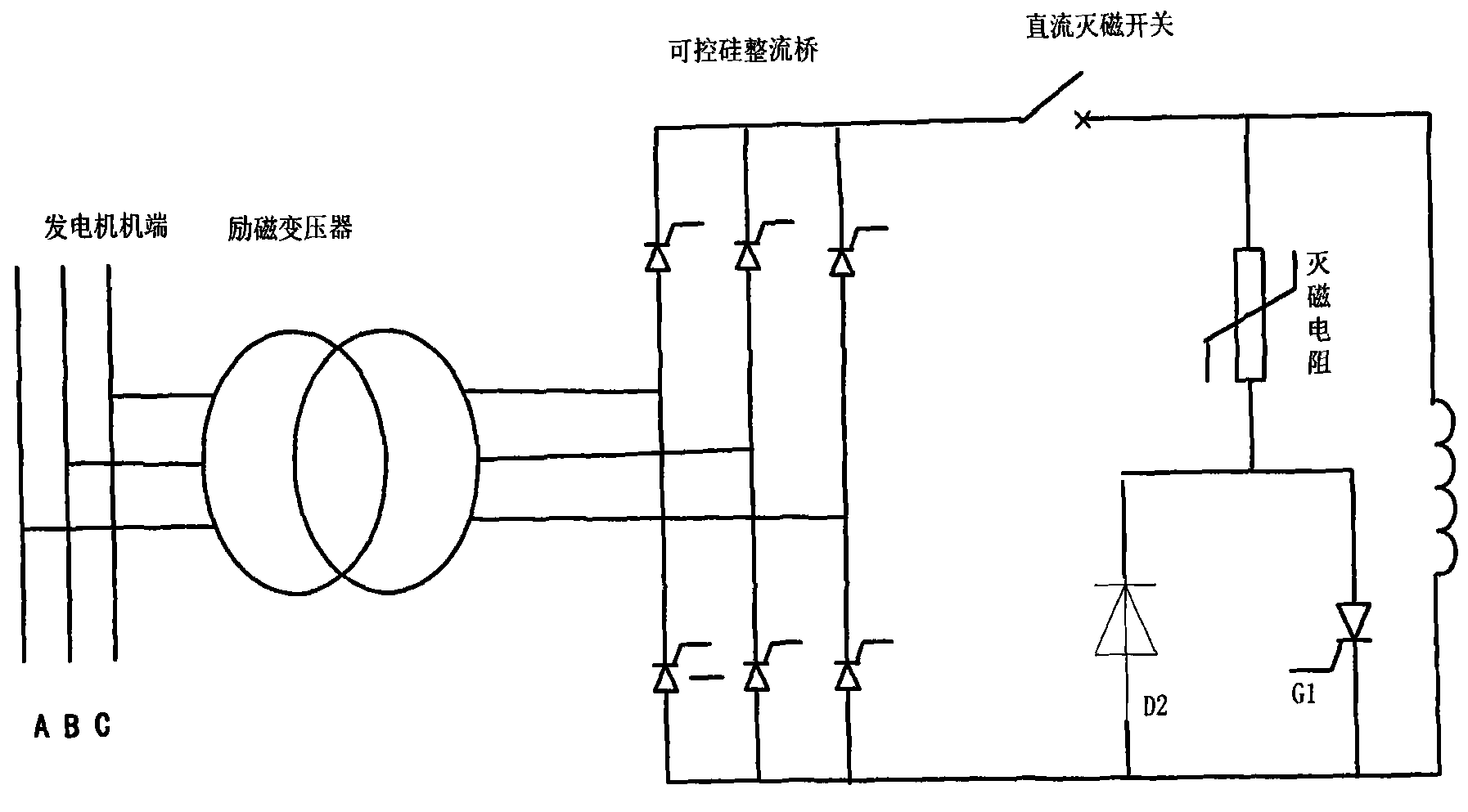
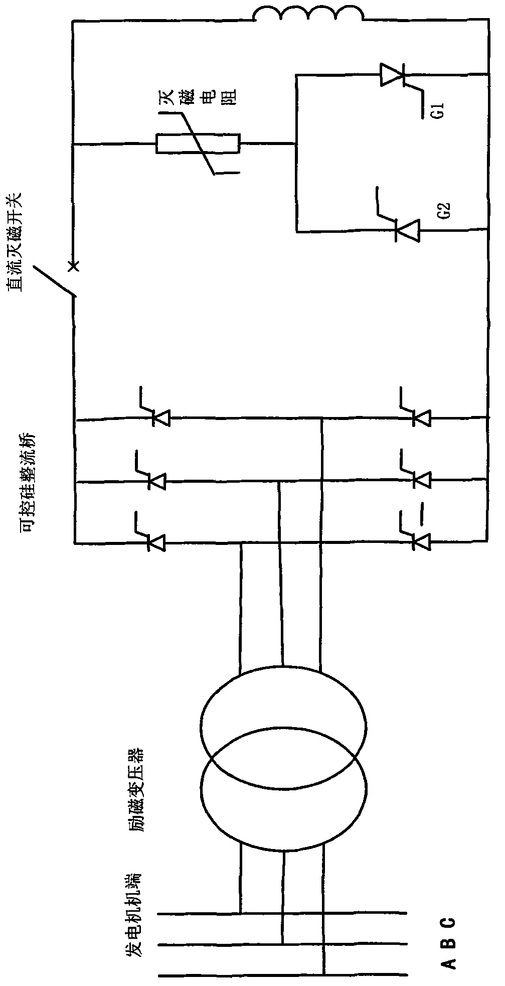
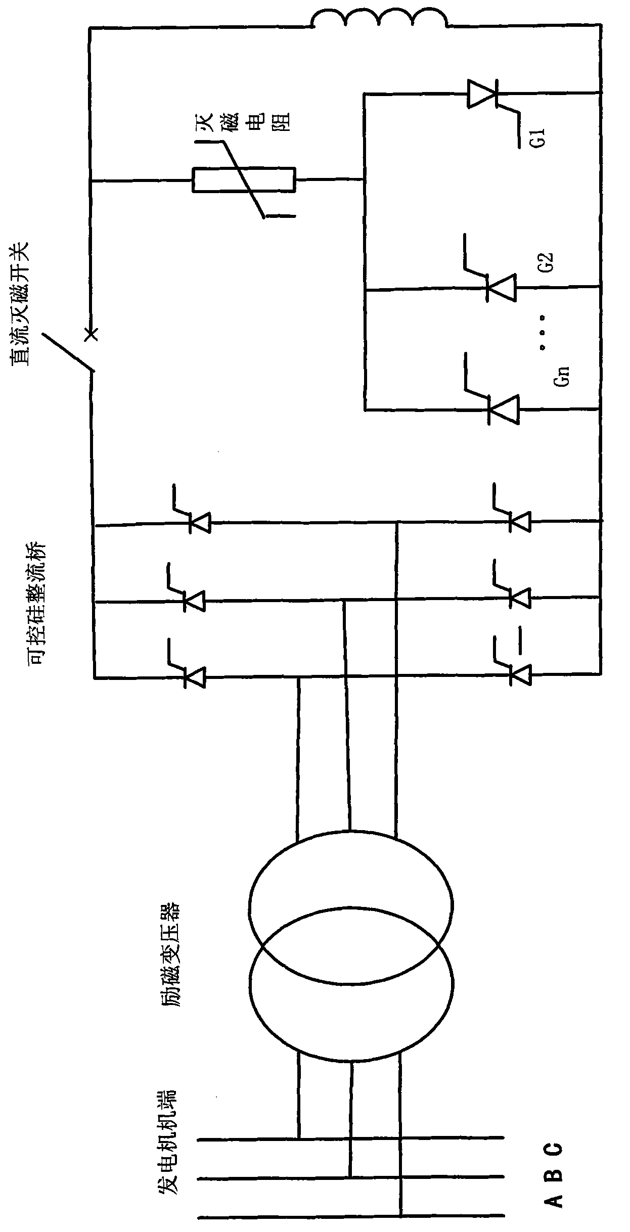
[0024] The present invention aims at the problem that the demagnetization current of large-capacity generator sets is too large, and a single thyristor cannot meet the requirements of safe and reliable demagnetization under the most serious working conditions. One or even multiple SCRs are connected in parallel to improve the flow capacity of the entire demagnetization circuit, that is, multiple SCR redundant demagnetization circuits. The basic characteristics of the de-excitation circuit are: first, multiple thyristors are connected in parallel in series with the non-linear resistance circuit in the de-excitation control circuit; second, the parallel thyristors use components of the same manufacturer and type, and It is very important to use high-parameter thyristor components as much as possible; thirdly, the characteristic parameters of each thyristor should be matched as well as possible, and it is best to confirm that the current sharing effect is good through relevant exp...


PUM


Abstract

The invention discloses a large current deexcitation loop based on silicon controlled rectifier (SCR) subject to multi-redundancy trigger control of a jumper. A generator end leads out an excitation three-phase alternating-current supply which combines an exciting transformer, a three-phase full-SCR rectifier bridge and a generator rotor winding to form a main loop; the output end of the SCR rectifier bridge is connected with a direct current deexcitation switch in series; and the two ends of the generator rotor winding are connected with an electronic jumper in parallel for deexcitation. The invention is characterized in that the electronic jumper comprises a deexcitation resistor and a forward and reverse SCR which is connected with the deexcitation resistor in series and comprises a forward SCR and n reverse SCRs which are connected with one another in parallel, wherein n is more than or equal to 2; and each SCR is triggered by a pulse loop corresponding to each SCR. The deexcitation loop not only effectively solves the technical problem of large capacity set and large current deexcitation, but also obviously improves the reliability of the whole deexcitation loop.

Description

technical field [0001] The invention relates to a high-reliability and high-current de-excitation method for a generator with a de-excitation protection function for the excitation system of a large-capacity generator set, and belongs to the technical field of generator excitation circuit control. Background technique [0002] In recent years, with the continuous increase of the unit capacity of generator sets, the excitation current on the rotor side of synchronous generators has become larger and larger. At present, the excitation current of large-capacity units under rated load is usually as high as 4000-8000A. When these generators have three-phase short-circuit faults, no-load false strong excitation and other harsh working conditions, the excitation current at the time of the fault will far exceed the excitation current under the rated load, and the maximum de-excitation current of the generator is usually required to reach More than tens of thousands of amperes, highe...

Claims


Application Information

Patent Timeline
IPC IPC(8): H02H7/06H02P9/12
Inventor 许其质许其品陈遗志郝勇
Owner NARI TECH CO LTD
Why Eureka
Try Eureka