Thread forming tap

A technology of cold forming and taps, which is applied in thread cutting tools, metal processing equipment, manufacturing tools, etc. It can solve problems such as incorrect size ratio, unoptimized, and different tap shapes, so as to reduce springback, inhibit wear, and improve tool quality. The effect of longevity

Active Publication Date: 2013-02-27
OSG
View PDF2 Cites 1 Cited by
  • Summary
  • Abstract
  • Description
  • Claims
  • Application Information

AI Technical Summary

Problems solved by technology

[0006] In addition, in the above-mentioned patent document 2, it is proposed that, for example, Image 6 The method of providing a large-diameter thread portion on all thread portions as shown, in this case, the load is distributed by repeatedly applying forming pressure to form an internal thread through a plurality of thread ridges (protrusions) of the large-diameter thread portion , but the large-diameter thread portion functions substantially as a full thread portion, which is the same as the case of forming an internal thread without back taper, so the rotational torque during tapping becomes large, which is not preferable.
Image 6 In order to clarify the change in the diameter dimension, the dimension of the vertical axis is enlarged with respect to the horizontal axis, but strictly speaking, the illustration is not a correct dimension ratio, and it is a change pattern of the diameter dimension, so it is different from the actual tap shape

Method used


Image

  • Thread forming tap
  • Thread forming tap
  • Thread forming tap

Examples


Embodiment

[0042] Hereinafter, embodiments of the present invention will be described in detail with reference to the drawings.

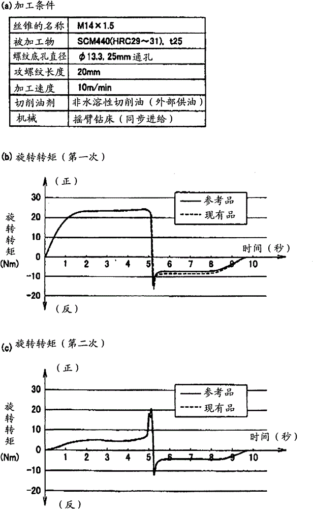
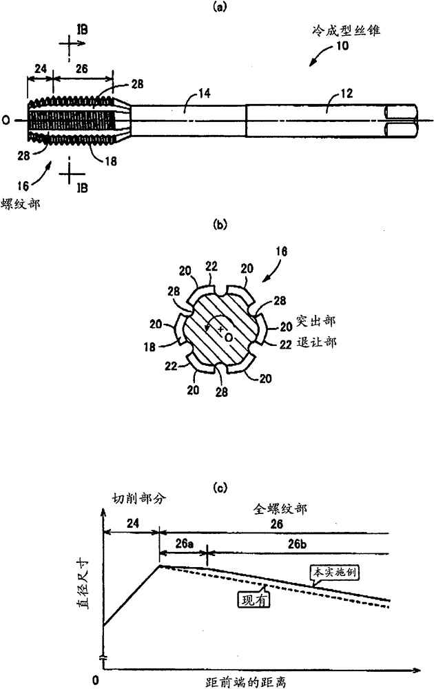
[0043] figure 1 It is a figure showing the cold forming tap 10 which is an embodiment of the present invention, (a) is a front view seen from a direction perpendicular to the axis O, and (b) is an enlarged view of the IB-IB cross section of (a) , (c) is a diagram showing a change pattern of the diameter dimension of the threaded portion 16 in the axial direction. The cold forming tap 10 is concentrically provided with a shank 12 mounted on the main shaft through a chuck not shown in this order and a head 14 with a diameter slightly smaller than the shank 12 in such a manner that it is connected in the axial direction in this order, and is used for cold forming. (Rolling) The threaded portion 16 of the internal thread. The threaded part 16 is formed in a polygonal shape consisting of sides bent outwards, and in this embodiment is a substantially regular hexa...


PUM


Abstract

A thread forming tap having a complete thread portion, formed with a predetermined back taper with that decreases rotational torque during tapping work, which reduces load acting on first complete protruding portions, formed at an extreme leading end of the complete thread portion, and thereby suppressing degradation in service life of the tool due to wear or the like

Description

technical field [0001] The present invention relates to a cold-formed tap, and particularly relates to a technique for improving tool life by suppressing wear of a protruding portion located at the leading end of a full thread portion. Background technique [0002] There is known a cold-forming tap which has a full thread portion and a cutting portion which is continuously provided with the full thread portion and whose diameter becomes smaller as it goes toward the front end, and protruding protrusions are alternately formed on these full thread portions and cutting portions. The external threads of the part and the relief part are screwed into the threaded bottom hole provided on the workpiece from the side of the cutting part, and the protruding part cuts into the inner wall surface part of the threaded bottom hole to make the inner wall surface part produce plasticity. deformed to form an internal thread. The tools described in Patent Documents 1 and 2 are examples, and...

Claims


Application Information

Patent Timeline
Patent Type & Authority Patents(China)
IPC IPC(8): B23P23/00B23G5/06
CPCB23G2200/32B23G7/02Y10T408/904Y10T408/9046Y10T408/9048
Inventor 山本浩典松下敬之
Owner OSG
Why Eureka
Try Eureka