Wire rope flaw detector

A flaw detection device and steel cable technology, applied in the direction of material magnetic variables, etc., can solve problems such as failure to detect steel cable damage, and achieve the effect of avoiding skin effect and high-precision damage

Active Publication Date: 2011-02-16
MITSUBISHI ELECTRIC CORP
View PDF2 Cites 6 Cited by
  • Summary
  • Abstract
  • Description
  • Claims
  • Application Information

AI Technical Summary

Problems solved by technology

However, in order to magnetically saturate the wire rope and extract the leakage magnetic flux, it is necessary to flow a current equivalent to that of the excitation coil or to increase the number of coil turns. Therefore, there is a problem that the size of the wire rope flaw detection device is larger than that of the permanent magnet excitation.
In addition, when the alternating magnetic flux passes through the cable, the magnetic flux concentrates on the surface of the cable due to the skin effect, so there is a problem that the damage inside the cable cannot be detected.

Method used


Image

  • Wire rope flaw detector
  • Wire rope flaw detector
  • Wire rope flaw detector

Examples


Embodiment 1

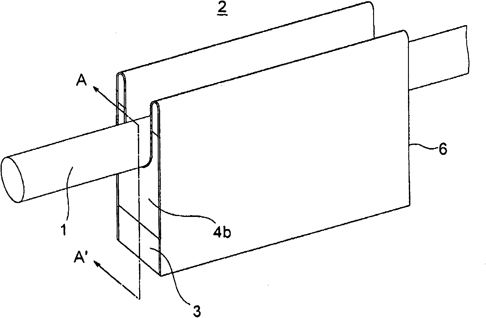
[0028] refer to Figure 1 to Figure 8 A wire cable flaw detection device according to Example 1 of the present invention will be described. figure 1 It is a perspective view showing the appearance of the wire rope flaw detection device according to the first embodiment of the present invention. In addition, in each figure from now on, the same code|symbol represents the same or a corresponding part.

[0029] exist figure 1 The middle table shows the steel cable 1 and the steel cable flaw detection device 2 . In addition, the back yoke 3, the permanent magnet 4b for a field, and the protection plate 6 are shown.

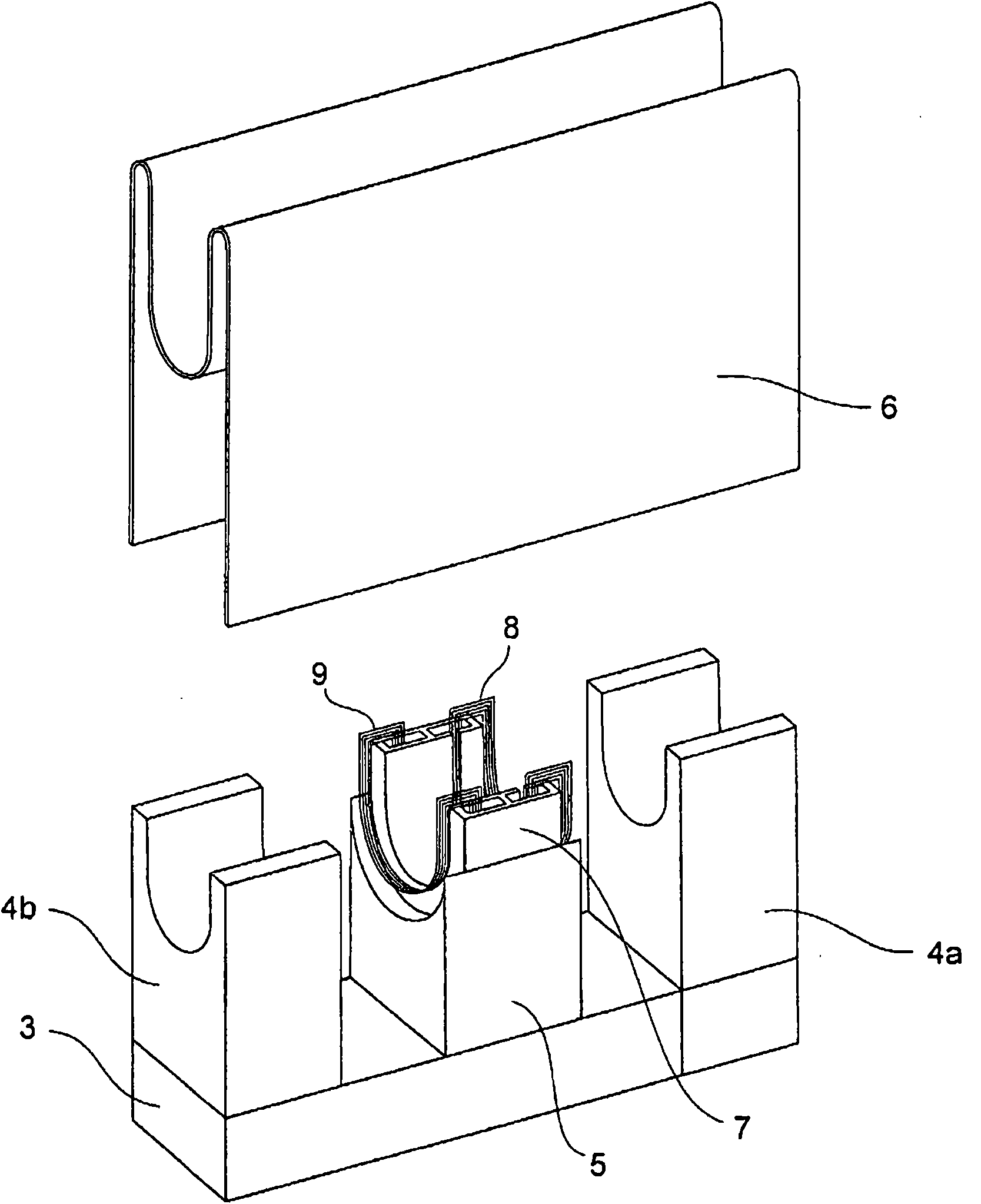
[0030] figure 2 yes means figure 1 A perspective view of the appearance of the wireline flaw detection device with the protective plate removed.

[0031] figure 2 The back yoke 3, the permanent magnets 4a and 4b for excitation, the support stand 5, the protection plate 6 removed from the wire rope flaw detection device, the magnetic circuit member 7, the dete...

Embodiment 2

[0051] refer to Figure 9 to Figure 11 A wire cable flaw detection device according to Example 2 of the present invention will be described. Figure 9 It is a diagram showing a partial configuration of a wire rope flaw detection device according to Example 2 of the present invention.

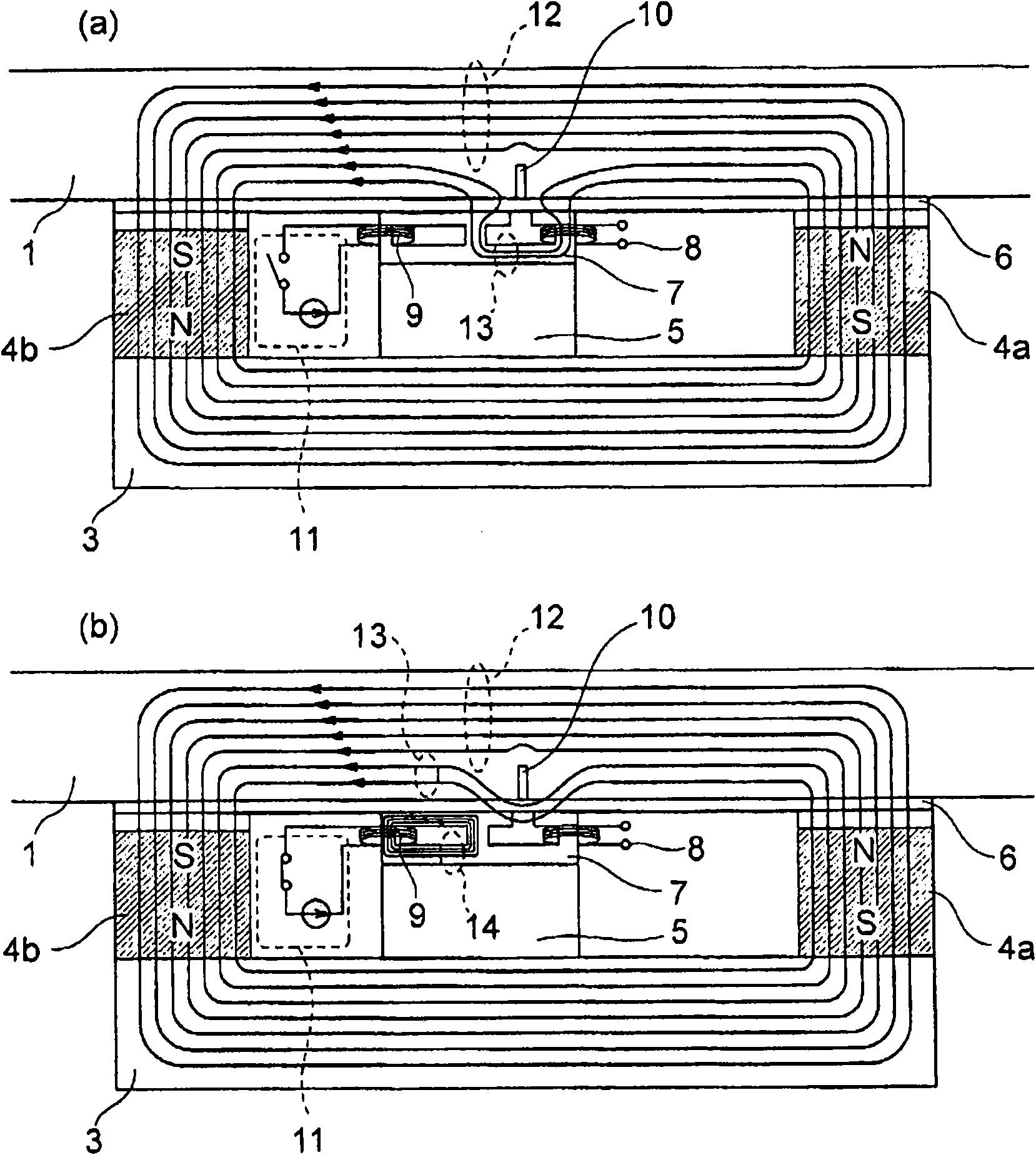
[0052] Should Figure 9 and image 3 Similarly, it means from figure 1 A cross-sectional view of the steel cable flaw detection device of Example 2 viewed along the line A-A'. Should Figure 9 It is a cross-sectional view taken along a plane including the central axis of the wire rope 1, and shows the flow of magnetic flux in the vicinity of the damaged portion of the wire rope. In addition, (a) shows a case where no current flows through the exciting coil, and (b) shows a case where a current flows through the exciting coil.

[0053] exist Figure 9 In the figure, the steel cable 1, the back yoke 3, the permanent magnets 4a and 4b for excitation, the supporting platform 5, the magnetic c...

Embodiment 3

[0062] refer to Figure 12 to Figure 14 A wire cable flaw detection device according to Example 3 of the present invention will be described. Figure 12 It is a diagram showing a partial configuration of a wire rope flaw detection device according to Example 3 of the present invention.

[0063] Should Figure 12 and image 3 Similarly, it means from figure 1A cross-sectional view of the steel cable flaw detection device of Example 3 viewed along the line A-A'. Should Figure 12 It is a cross-sectional view taken along a plane including the central axis of the wire rope 1, and shows the flow of magnetic flux in the vicinity of the damaged portion of the wire rope. In addition, (a) shows a case where no current flows through the exciting coil, and (b) shows a case where a current flows through the exciting coil.

[0064] exist Figure 12 In the figure, the steel cable 1, the back yoke 3, the permanent magnets 4a, 4b for excitation, the supporting platform 5, the magnetic ...


PUM


Abstract

A magnetic flux generated by current excitation is allowed to run over a portion of the magnetic path of a leakage magnetic flux or the entire magnetic path thereof. The amount of the magnetic flux generated by the current excitation is changed in terms of time to change the amount of the leakage magnetic flux crossing a detection coil, an induction voltage is generated in the detection coil, and consequently a flaw can be detected even in the case where there is no relative rate between a wire rope and a wire rope flaw detector. Further, the shape of the magnetic path and the number of ampere turns of the exciting coil are set to be appropriate to prevent the magnetic flux generated by the current excitation from running through the detection coil and make the magnetic flux get balanced out. Thus, noise superimposition to the detection coil generated by current excitation can be prevented.

Description

technical field [0001] The present invention relates to a wire rope flaw detection device for detecting breakage of a wire rope suspending a car of an elevator or the like or a breakage of a wire rod (hereinafter referred to as a damaged part of the wire rope). Background technique [0002] The existing steel cable flaw detection device is composed of an exciting core with at least two magnetic poles arranged close to the steel cable, a permanent magnet for excitation embedded in the exciting core, and a detection coil arranged between the two magnetic poles. (For example, refer to Patent Document 1). Conventional wire rope flaw detection devices detect the damaged portion of the wire rope by magnetically saturating the wire rope with two magnetic poles to generate leakage magnetic flux from a damaged portion such as a wire notch, and detecting the leakage magnetic flux with a detection coil. [0003] Furthermore, there is an example in which an electromagnet is used to exc...

Claims


Application Information

Patent Timeline
Patent Type & Authority Applications(China)
IPC IPC(8): G01N27/83
CPCG01N27/83
Inventor 吉冈孝笹井浩之西依幸一郎
Owner MITSUBISHI ELECTRIC CORP
Why Eureka
Try Eureka