
Leftward/rightward rotating punching machine

A technology of punching machine and power mechanism, applied in the field of punching machine, can solve the problems of misalignment, slow punching speed, waste of raw materials, etc.

Inactive Publication Date: 2011-03-02
JINFANGTONG WELDING EQUIP LUTAI ECONOMIC DEV ZONE
View PDF6 Cites 4 Cited by
  • Summary
  • Abstract
  • Description
  • Claims
  • Application Information

AI Technical Summary

Problems solved by technology

Domestic counterparts have invested manpower and material resources in the development of the above-mentioned problems, but they are not very satisfactory. The reason is mainly that holes of 1-2 mm are punched on the copper rods with a length of about 45 mm and a diameter of about 9 mm. Smaller, and the diameter of the hole to be punched is also very small, so the result of punching the hole is often biased, which not only consumes raw materials, but also the efficiency of punching is very low
[0003] The traditional drilling methods include bench drills and lathes. Although the efficiency of traditional bench drills is much higher than that of hand drills, the drilled holes often deviate from the original position due to the high impact force of the drill. Position, because only the drill bit rotates in one direction, the drilling rate is slow, and at the same time, because the drilled hole is not very vertical, resulting in a high scrap rate; the lathe is used for drilling, because the drilling rate is slow, so it often occurs when drilling. Uneven force directly leads to poor concentricity of the drilled holes
[0004] When drilling, the traditional method of fixing the workpiece is to use a three-jaw chuck or tooling. However, using the above fixing method, after clamping the workpiece, it is necessary to align it again, which greatly wastes time.

Method used


Image

  • Leftward/rightward rotating punching machine
  • Leftward/rightward rotating punching machine
  • Leftward/rightward rotating punching machine

Examples


Embodiment Construction

[0023] The punching machine of the present invention can be applied to various fields such as shipyards, steel structures, chemical industry, and automobile manufacturing.

[0024] First, refer to the attached Figure 4 , with Figure 4 The main principle of the present invention is shown. The present invention mainly performs fast and accurate drilling on the workpiece by rotating the relevant parts of the upper body to the left and the relevant parts of the lower body to the right during the punching operation. Of course, the rotation directions of the upper body and the lower body are not fixed, as long as the above two rotation directions are opposite.

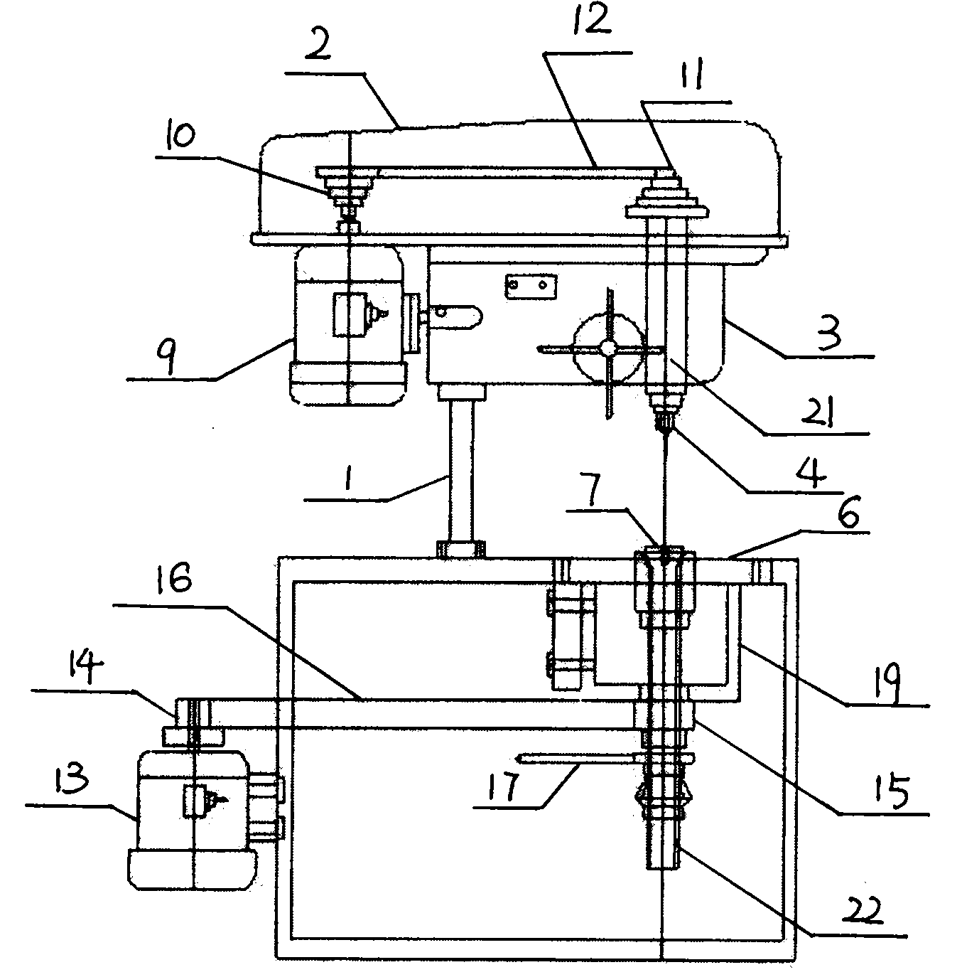
[0025] Refer to attached figure 1 , with figure 1 The overall structure of the punching machine of the present invention is shown. The punching machine includes an upper body, a column 1 and a lower body. The column 1 is used as a supporting part of the present invention and is connected between the upper body and the l...


PUM


Abstract

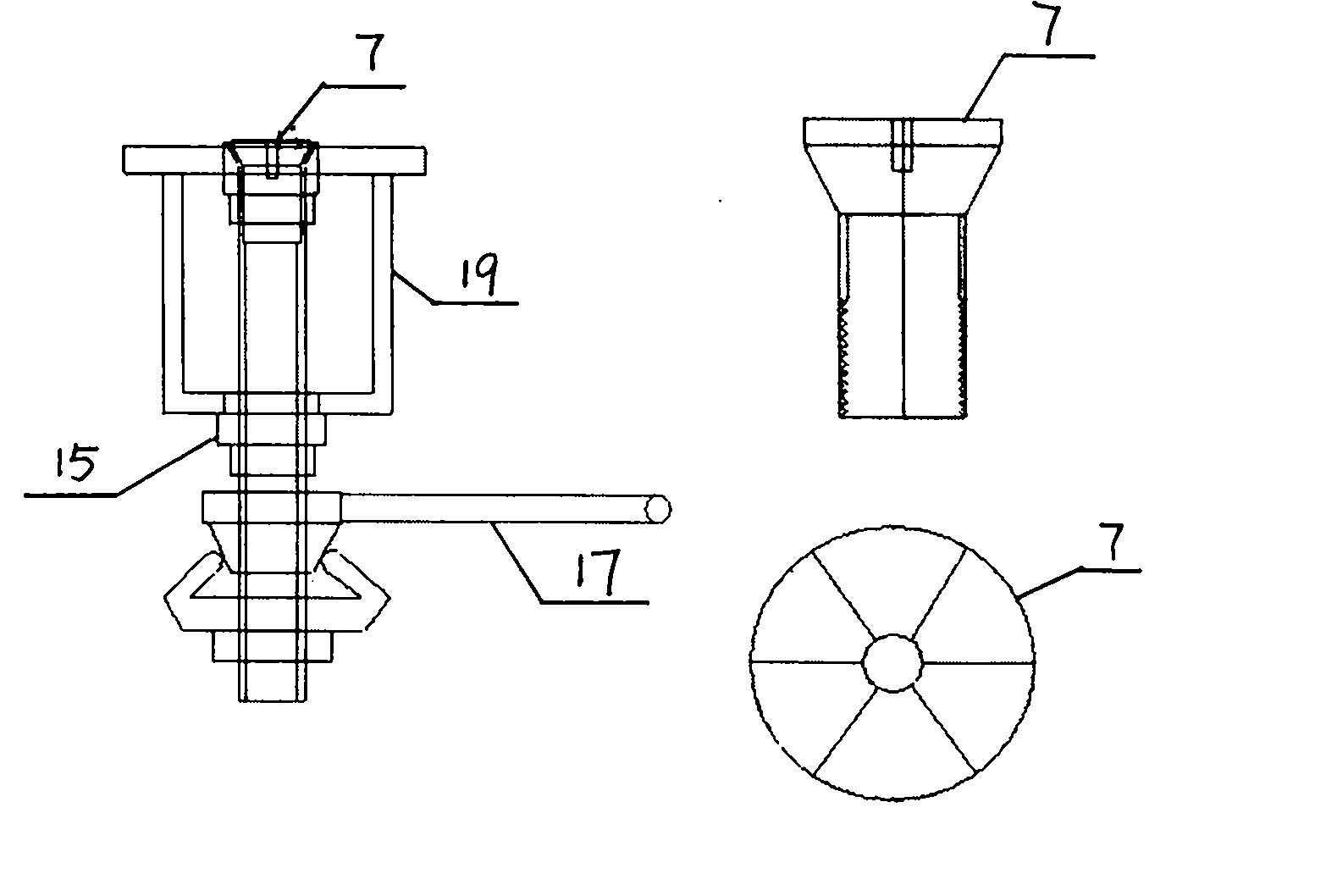
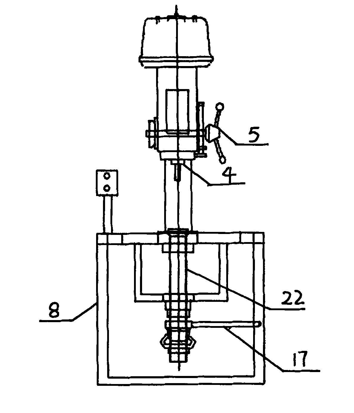
The invention relates to a leftward / rightward rotating punching machine, comprising an upper body, a supporting part and a lower body, wherein the supporting part is connected between the upper body and the lower body. The punching machine is characterized in that the upper body comprises an upper housing, a punching part, a wrench and a power mechanism 1; the punching part comprises a spindle 21, a chuck and a drill; the chuck is positioned at the front end of the spindle 21 and is used for fixing the drill; the wrench is connected with the punching part and is used for pushing the punching part; the power mechanism 1 is connected with the punching part and is used for providing power for rotation of the punching part; the lower body comprises a stage, a spindle 22 and a power mechanism 2, wherein the stage comprises a clamping device; the clamping device is positioned on the stage and is used for clamping the workpiece; the spindle 22 is connected with the clamping device on the stage; the power mechanism 2 is connected with the spindle 22; when the punching machine punches holes, the punching part rotates; and meanwhile, the spindle 22 drives the clamping device to further drive the workpiece to rotate oppositely relative to the punching part.

Description

technical field [0001] The invention relates to a punching machine, in particular to a punching machine which can rotate left and right. Background technique [0002] In recent years, with the rapid development of manufacturing industries such as automobiles and ships and the chemical industry, the scope of use of punching machines has become wider. Therefore, how to drill holes quickly and accurately on the basis of reducing labor intensity has become an a big problem. Domestic counterparts have invested manpower and material resources in the development of the above-mentioned problems, but they are not very satisfactory. The reason is mainly that holes of 1-2 mm are punched on the copper rods with a length of about 45 mm and a diameter of about 9 mm. Smaller, and the diameter of the hole to be punched is also very small, so the result of punching the hole is often biased, which not only consumes raw materials, but also the efficiency of punching is very low. [0003] The...

Claims


Application Information

Patent Timeline
IPC IPC(8): B23B39/00B23B47/00B23B47/04B23Q1/25B23Q3/06
Inventor 汪会义
Owner JINFANGTONG WELDING EQUIP LUTAI ECONOMIC DEV ZONE
Learn More