
Eureka
For R&D, Eureka makes reading and utilizing patents & technical documents easy.
Eureka AIR
Designed for self-driven R&D workflows. Generate viable solutions, solve complex R&D challenges, empower your innovation with AI.

Eureka Materials
Designed for material experts only. Revolutionize your material R&D, from search, analyze, to developing new materials.

TechResearch
Generate reliable direction feasibility study reports for your R&D in just a few steps.

TechSeek
Discover and master advanced knowledge NOW. Basics, ideas, possibilities, all at once.

TechMind
As an expert in R&D Theories, TechMind can generates customized viable solutions instantly.

TechRisk
Analyze your overall solution with one click, know your potential R&D risks in advance.

TechMonitor
Get weekly tech updates, stay abreast of the latest tech innovations and key insights.
Servo differential transmission device for gear slotting machine
A transmission device and gear shaping machine technology, applied in the direction of gear tooth manufacturing device, gear cutting machine, gear teeth, etc., can solve the problems of easy wear of spiral guide rail, increase power consumption, and inability to adapt to processing, etc., to overcome easy wear and eliminate friction , good synchronization effect
- Summary
- Abstract
- Description
- Claims
- Application Information
AI Technical Summary
Problems solved by technology
Method used
Image


Examples
Embodiment 1
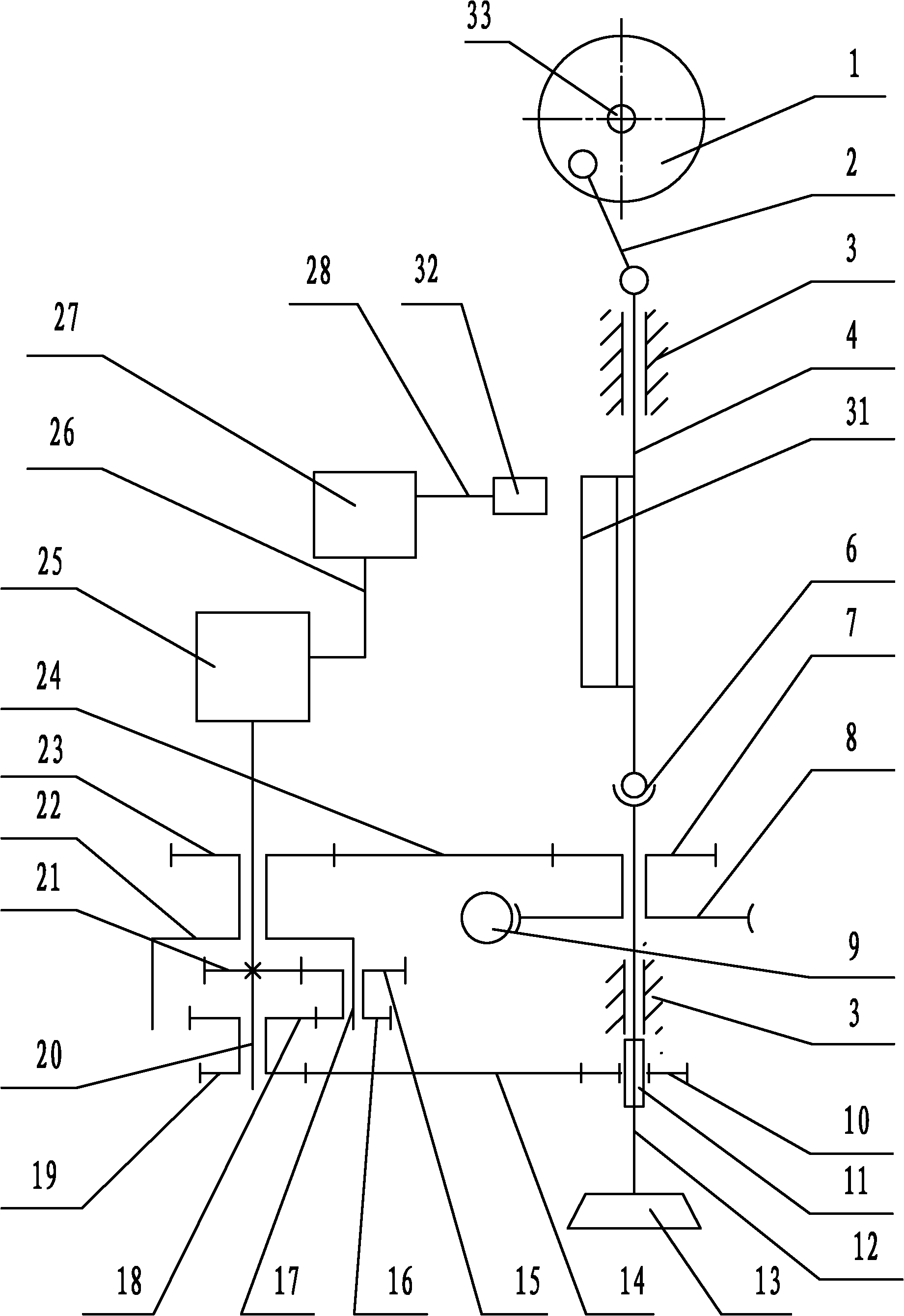
[0021] like figure 1 As shown, the servo differential gear shaping machine transmission device includes a crank slider mechanism, a displacement detection device, a servo transmission device, a differential transmission device, a worm gear transmission mechanism, a cutter shaft, and a cutter shaft transmission mechanism;
[0022] The slider crank mechanism comprises crank disc 1, connecting rod 2, slide block 4, crank rotary shaft 33, and crank rotary shaft 33 is supported on the gear shaping machine tool body 3 by bearing (crank rotary shaft 33 can rotate), crank disc 1 and The crank shaft 33 is fixedly connected, the crank disc 1 and the crank shaft 33 are perpendicular to each other, and one end of the crank shaft 33 is connected with the output shaft of the main motor of the gear shaping machine tool by a coupling or transmission mechanism (the crank disc is formed by the main motor of the gear shaping machine tool). drive, the main motor of the gear shaping machine tool i...
Embodiment 2
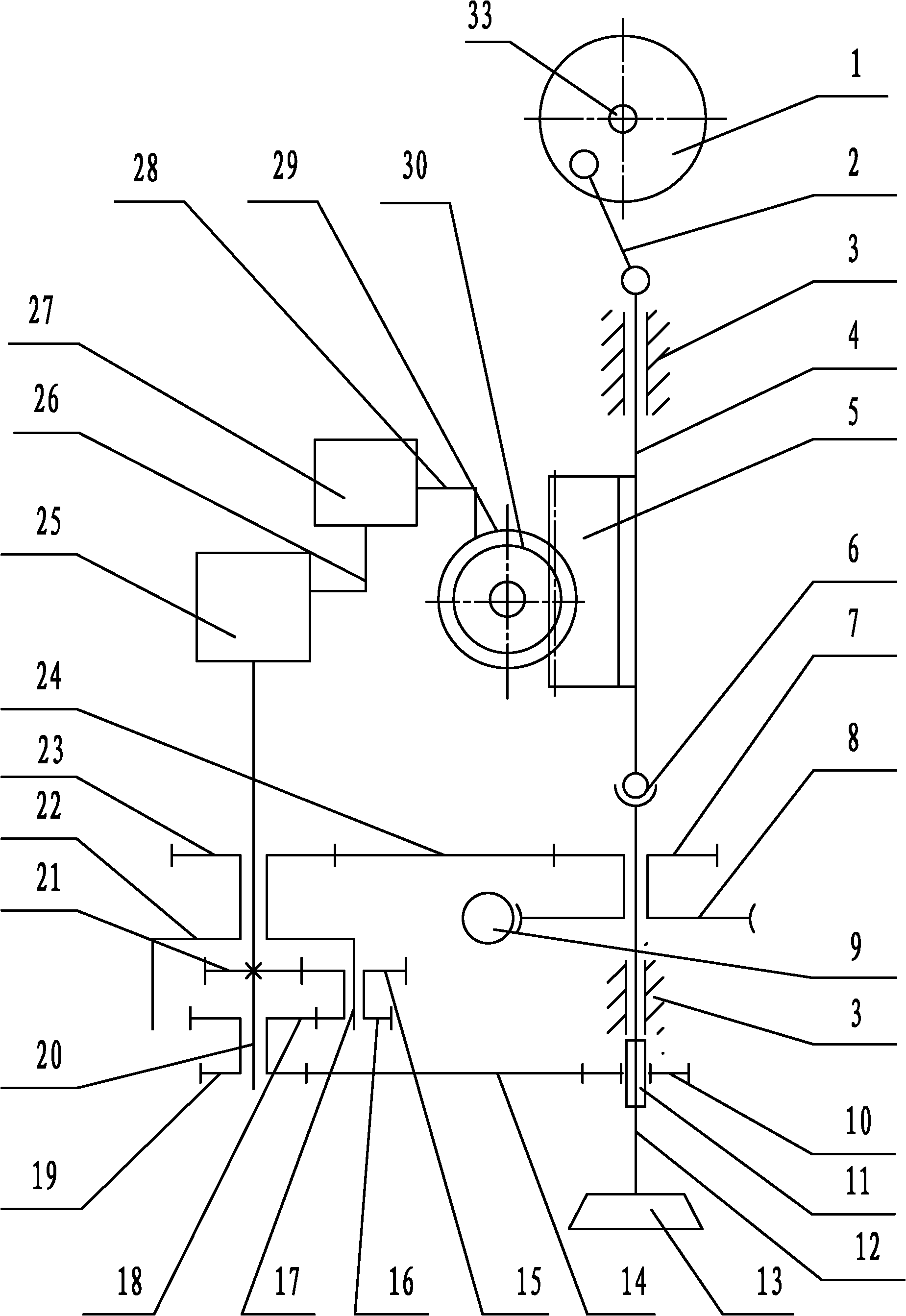
[0036] like figure 2 As shown, it is basically the same as Embodiment 1, except that the displacement detection device includes a grating scale 31 and a grating reading head 32, and the grating scale 31 is fixedly installed on the slider 4 of the slider crank mechanism; the grating reading head 32 is located at At the grating scale 31, the output end of the grating reading head 32 is connected with the input end of the signal processing and controller 27 of the servo transmission device by the second cable 28;
[0037] When the slider 4 and the grating scale 31 move up and down together, the grating reading head 32 reads the displacement signal of the up and down movement, and transmits it to the signal processing and controller 27, thereby controlling the movement of the motor 25, and then driving the difference through the coupling The differential spindle 20 of the drive transmission.
[0038] figure 2 Among them, the displacement signal generating part adopts a grating...
Embodiment 3
[0040] It is basically the same as Embodiment 1 or Embodiment 2, except that the cutter shaft transmission mechanism includes a sliding sleeve 11 and a cutter shaft driving wheel 10, the sliding sleeve 11 is fixedly installed on the cutter shaft 12, and the cutter shaft driving wheel 10 is set on the On the sliding sleeve 11, the sliding sleeve 11 is provided with a key or a raised slider along the axial direction of the cutter shaft 12, and a chute is arranged in the hole on the cutter shaft drive wheel 10, and the key or the raised slider is located in the chute. Inside (both linear sliding between the cutter shaft transmission wheel 10 and the sliding sleeve 11, and simultaneously the cutter shaft transmission wheel 10 can drive the sliding sleeve 11 and the cutter shaft 12 to rotate together).
PUM
 Abstract
Description
Claims
Application Information
 - R&D Engineer
- R&D Manager
- IP Professional
- Industry Leading Data Capabilities
- Powerful AI technology
- Patent DNA Extraction
Browse by: Latest US Patents, China's latest patents, Technical Efficacy Thesaurus, Application Domain, Technology Topic, Popular Technical Reports.
© 2024 PatSnap. All rights reserved.Legal|Privacy policy|Modern Slavery Act Transparency Statement|Sitemap|About US| Contact US: help@patsnap.com