Hybrid power apparatus

A technology of hybrid power and driving force, which is applied in power units, hybrid vehicles, pneumatic power units, etc., and can solve problems such as vehicles being unable to drive.

Inactive Publication Date: 2011-03-02
AISIN AI CO LTD +2
View PDF5 Cites 25 Cited by
  • Summary
  • Abstract
  • Description
  • Claims
  • Application Information

AI Technical Summary

Problems solved by technology

When the gear is switched, if the two friction clutches are engaged at the same time due to the misoperation of the control system, the switching mechanisms of the two gear transmission mechanisms will lock each other and cannot rotate, so that the engine stops suddenly, and the vehicle cannot driving

Method used


Image

  • Hybrid power apparatus
  • Hybrid power apparatus
  • Hybrid power apparatus

Examples


Embodiment Construction

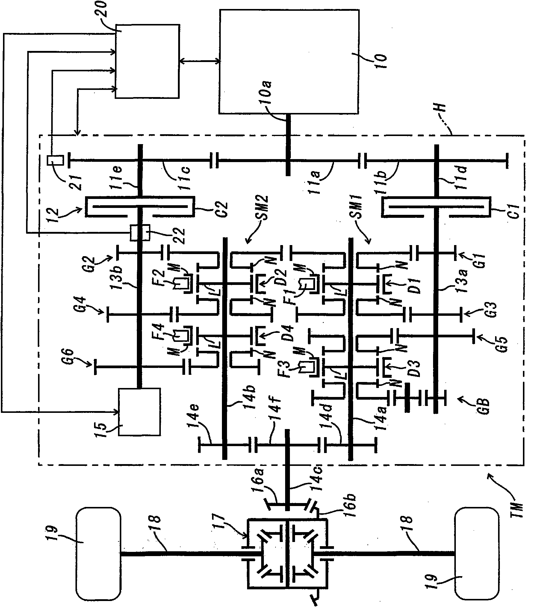
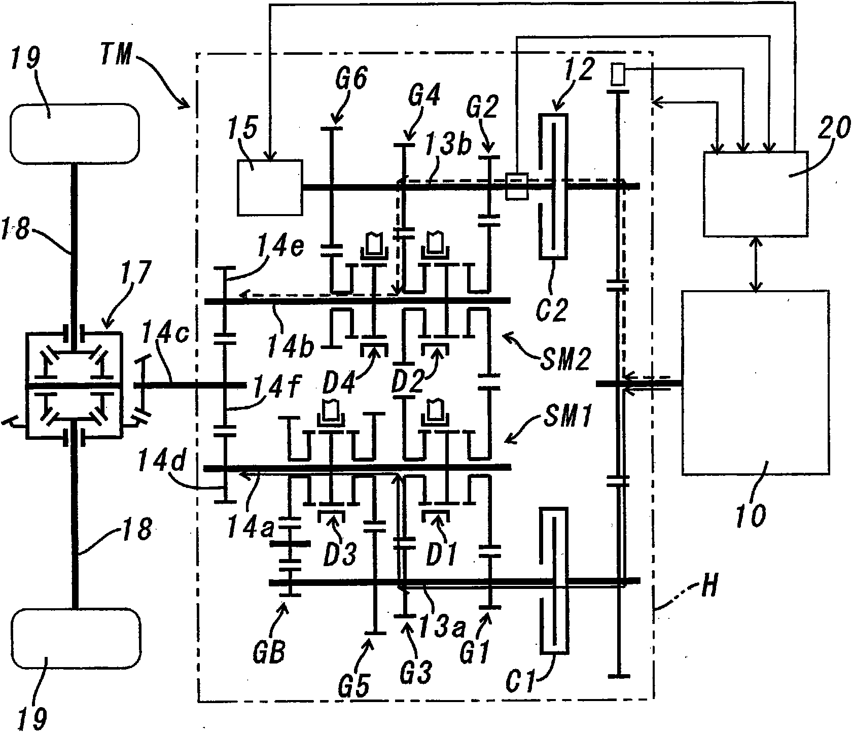
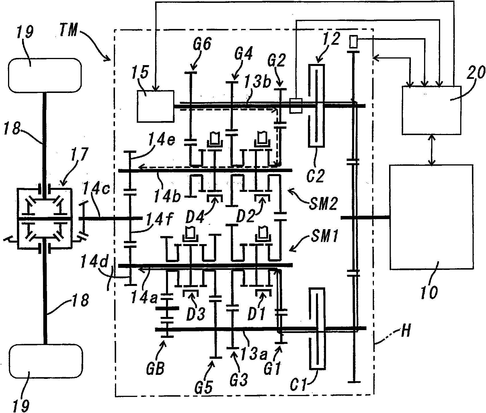
[0017] Below, refer to Figure 1-Figure 4 , the first embodiment of the hybrid power device of the present invention will be described. In the first embodiment, the hybrid device of the present invention is applied to figure 1 Shown is an automatic transmission TM with 6 forward speeds and 1 reverse speed.

[0018] This automatic transmission TM is a dual-clutch type. In the gearbox H, the first input shaft 13a and the second input shaft 13b, which are arranged in parallel with each other and can rotate freely, are connected to the engine 10 via the first friction clutch C1 and the second friction clutch C2. The output shaft 10a is connected. The input member of the first friction clutch C1 is coupled to the support shaft 11d of the driven gear 11b, and the drive gear 11a that rotates integrally with the output shaft 10a of the engine 10 meshes with the driven gear 11b. Similarly, the input member of the second friction clutch C2 is coupled to the support shaft 11e of the d...


PUM


Abstract

When a gear stage selected by the gear transmission mechanism of a first drive train or a second drive train is switched to a gear stage of a gear transmission mechanism of the other drive train, deceleration in the rotational speed of the engine detected by a rotational speed sensor is compared with a preset upper limit. If the upper limit is exceeded, a motor generator connected to the input shaft of the second drive train is started as an electric motor, and a load torque is generated to cancel the torque input from the engine to said input shaft, and in this state the gear stage of the gear transmission mechanism of said other drive train is disengaged.

Description

technical field [0001] The present invention relates to a hybrid power device, in particular to a hybrid power device suitable for a dual-clutch vehicle transmission. Background technique [0002] In Japanese Patent Laid-Open No. 2005-186931, a hybrid device using such a dual clutch is proposed. The hybrid device has a first input shaft and a second input shaft which are coaxially arranged and can rotate relative to each other and selectively transmit the driving force of the engine through the dual clutch, and are respectively installed on the first output shaft arranged in parallel with the two input shafts. The first gear transmission mechanism and the second gear transmission mechanism on the shaft and the second output shaft are connected to the second output shaft, and when power is supplied, they are used as motors to drive the drive wheels connected to the first output shaft or the second output shaft , which in turn acts as a generator to charge the battery when dr...

Claims


Application Information

Patent Timeline
Patent Type & Authority Applications(China)
IPC IPC(8): B60W10/10B60K6/48B60K6/547B60L11/14B60W10/02B60W10/04B60W10/08B60W20/00F16H61/18F16H59/14F16H59/16F16H59/42F16H59/48F16H61/688B60L50/16B60W30/18
CPCY02T10/6286Y02T10/6217F16H2200/0052F16H3/089B60W10/06B60K6/387F16H2059/147B60K6/547F16H59/14F16H2061/1204B60W10/113B60K6/36F16H2200/0008Y02T10/70B60L11/123B60W10/08F16H61/688B60Y2400/428F16H3/006Y02T10/6221B60L2240/441F16H2003/0931B60L2240/423F16H2061/0433B60K6/48B60W2710/083B60W20/00B60L11/14Y02T10/7077Y02T10/642B60W2510/0638B60W30/19B60L50/61B60L50/16Y10T74/19014Y02T10/62Y02T10/64Y02T10/7072B60W20/40B60W20/30B60W10/02
Inventor 丹波俊夫福原裕一佐佐木环丰良幸男大村雅洋
Owner AISIN AI CO LTD
Why Eureka
Try Eureka