Ice making unit for flow down type ice maker

An ice making machine and ice making plate technology, which is applied in the directions of ice making, ice making, lighting and heating equipment, etc., can solve the problems such as the lengthening of the upper and lower dimensions of the ice making plate, the inability to use ice cubes, the need for time, etc., to achieve ice making. Ability-enhancing effect

Active Publication Date: 2013-04-10
HOSHIZAKI ELECTRIC CO LTD
View PDF1 Cites 0 Cited by
  • Summary
  • Abstract
  • Description
  • Claims
  • Application Information

AI Technical Summary

Problems solved by technology

[0006] In the structure in which protrusions are provided on the ice-making surface like the above-mentioned downflow ice machine, if the ice cubes grow to the position where they contact the protrusions when the ice-making operation is completed, the ice along the ice-making surface cannot be used during the deicing operation. The velocity of the slide makes the ice cube touch the protrusion, and the aforementioned inhibition of falling due to the surface tension of the dissolved water becomes significant
Therefore, the interval in the vertical direction of the evaporation tube arranged on the back side of the ice-making plate is increased so that the ice cubes will not grow to the position where the protrusion contacts when the ice-making operation is completed. However, the following disadvantages are pointed out in this case: The vertical dimension of the ice plate itself becomes longer, the installation space of the ice making unit in the vertical direction becomes larger, and the size of the ice machine itself is also increased.
Therefore, there is a problem that it takes time to melt the frozen surface of the uppermost ice cube than the evaporator tube, and the other parts of the ice cube melt excessively.
Therefore, when a plurality of ice-making units are arranged in parallel to form an ice-making unit, a disadvantage has been pointed out that in order to prevent ice cubes that fall while rotating between the opposing ice-making plates from staying and causing blockage , it is necessary to increase the interval between adjacent ice making parts, so that the installation space of the ice making parts in the ice making unit in the parallel direction becomes larger, and the ice making machine also becomes larger

Method used


Image

  • Ice making unit for flow down type ice maker
  • Ice making unit for flow down type ice maker
  • Ice making unit for flow down type ice maker

Examples


Embodiment

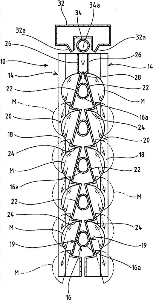
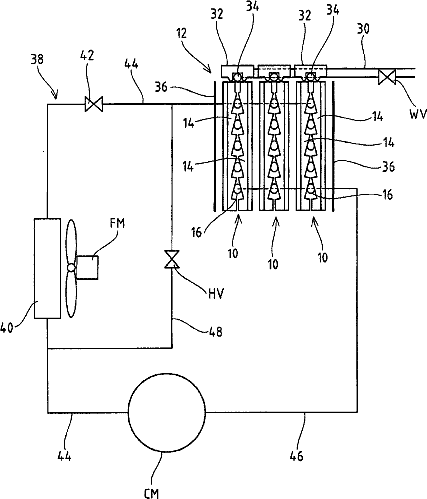
[0024] figure 1 It is a longitudinal sectional side view showing the ice making part 10 of the embodiment of the present invention, figure 2 It is a schematic configuration diagram of a downflow ice machine having an ice making unit 12 configured by arranging a plurality of ice making units 10 in parallel. in addition, image 3 is the overall representation figure 1 The schematic perspective view of the ice making part 10 shown. In the downflow type ice machine, the ice making unit 12 is arranged above the ice storage chamber (none of which is shown) divided into the inside of the heat insulation box, and the ice cubes M made by the ice making unit 12 are discharged and stored below. in the ice storage compartment. Such as figure 1 and image 3 As shown, each ice making unit 10 constituting the ice making unit 12 includes: a pair of ice making plates 14, 14 arranged longitudinally; 16. Such as Figure 4 As shown, the laterally extending portion 16a of the evaporating...


PUM


Abstract

By promptly separating ice blocks from ice making plates, ice making capacity is improved and also downsizing is sought. Ice making portions 10 are provided with a pair of ice making plates 14, 14 disposed vertically and an evaporation tube 16 disposed between back faces, facing each other, of both ice making plates 14, 14. On surfaces of the ice making plates 14, a plurality of vertically extending projected rims 18 are formed at a predetermined interval across the width, and by these projected rims 18, a plurality of ice making regions 20 are spaced apart widthwise and the plurality of them are defined. The ice making plates 14 facing the ice making regions 20 are configured to be provided consecutively with vertically multi steps of inclined portions 22 inclined from a back side towards a front side as directed downwardly, and are disposed to make contact with horizontal extensions 16a of the evaporation tube 16 at an approximately vertically intermediate position on a back face of each inclined portion 22.

Description

technical field [0001] The present invention relates to an ice making unit of a downflow type ice maker that generates ice cubes in the ice making region by supplying ice making water down to the ice making region of an ice making plate provided with an evaporating tube on the back. Background technique [0002] As an ice maker that automatically makes ice cubes, there is known a downflow ice maker in which a pair of ice making plates are placed opposite to each other across an evaporating tube constituting a refrigeration system in an ice making section. The ice section constitutes the ice making unit, and during the ice making operation, the ice making water is supplied down to the surfaces (ice making surfaces) of the ice making plates cooled by circulating the refrigerant supplied to the evaporating tubes, As a result, ice cubes are generated, and the ice cubes are shifted to the deicing operation, and the ice cubes are detached and dropped to be discharged (for example,...

Claims


Application Information

Patent Timeline
Patent Type & Authority Patents(China)
IPC IPC(8): F25C1/12
CPCF25C1/12
Inventor 山口弘城若槻勇二
Owner HOSHIZAKI ELECTRIC CO LTD
Why Eureka
Try Eureka