Saddle-shaped pipe end cutting device

A pipe end cutting device, saddle type technology, applied in welding equipment, gas flame welding equipment, metal processing equipment, etc., can solve problems such as affecting the stability and safety of equipment, unfavorable popularization and use, and high structural layout requirements. , to achieve the effect of expanding the cutting operation range, easy purchase of casters, and light overall movement

Active Publication Date: 2013-04-24
WUXI HUAGUANG IND BOILER
View PDF3 Cites 0 Cited by
  • Summary
  • Abstract
  • Description
  • Claims
  • Application Information

AI Technical Summary

Problems solved by technology

To use this kind of equipment, it is necessary to fix the tubular workpiece at a certain height and arrange it as a cantilever; the transmission mechanism needs to be arranged on the equipment to meet the rotary motion of the cutting torch around the axis of the workpiece; The balance and stability of the cutting machine requires high structural layout; when adjusting and changing the angle of the cutting groove, the cutting torch protrudes too far forward, and it is difficult to ensure the stability of its one-round rotation; while the cutting torch rotates at a constant speed, the Cutting, rotating to different positions on the circumference of the workpiece, the flow speed of the cut slag is different, and the direction of the slag on both sides of the workpiece is also inconsistent, so the required cutting speed and torch inclination angle are also different. Existing equipment The required speed and angle adjustment cannot be met, or the adjustment is very difficult to achieve, and it is easy to affect the stability and safety of the equipment when adjusting the angle; for workpieces with different pipe diameters and large differences, different positioning shells are required And drive the rotating mechanism, so that the weight of cutting equipment with large pipe diameters increases sharply, or it is necessary to use high-strength alloy materials to reduce the total weight of the equipment, the cost is high, it is difficult to place the pipe end during cutting, and the moving operation after cutting is also difficult; Cutting flush pipe ends requires changing the profile and shutting down the operation
[0006] There are also equipment developed by equipment manufacturers that use numerical control programming to cut and process pipe ends, and the manufacturing cost of the equipment is higher, which is not conducive to a large number of rapid popularization and use

Method used


Image

  • Saddle-shaped pipe end cutting device
  • Saddle-shaped pipe end cutting device
  • Saddle-shaped pipe end cutting device

Examples


Embodiment Construction

[0017] The present invention will be further described below in conjunction with specific drawings and embodiments.

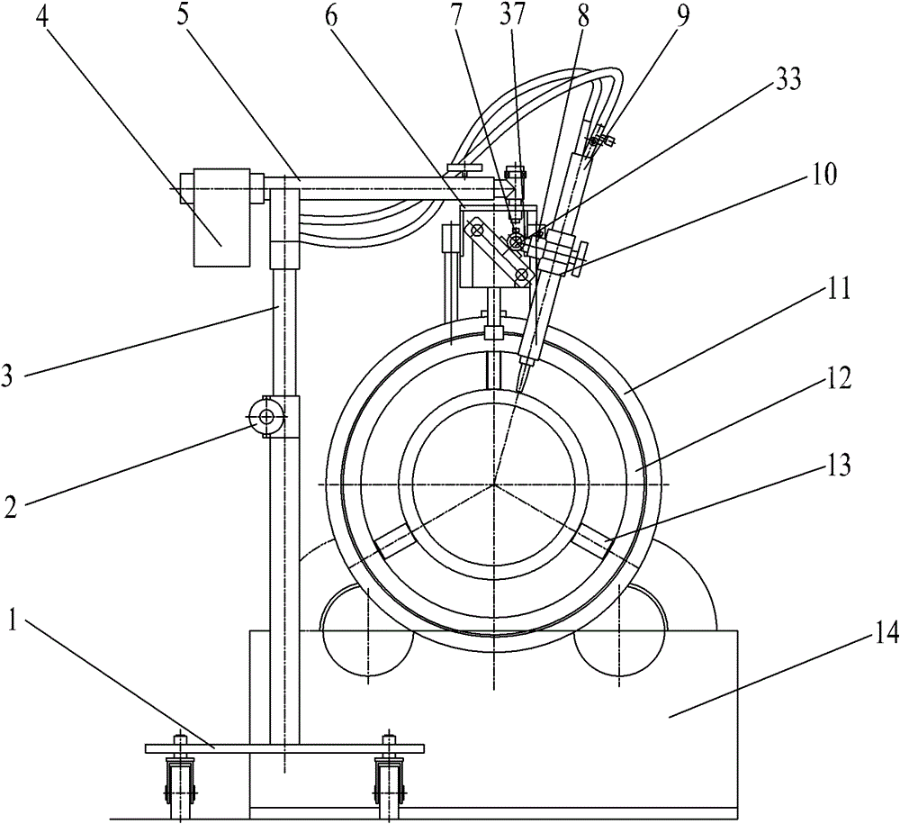
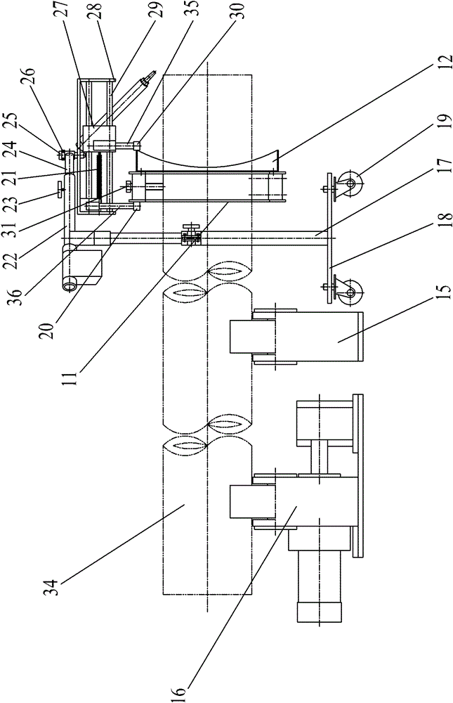
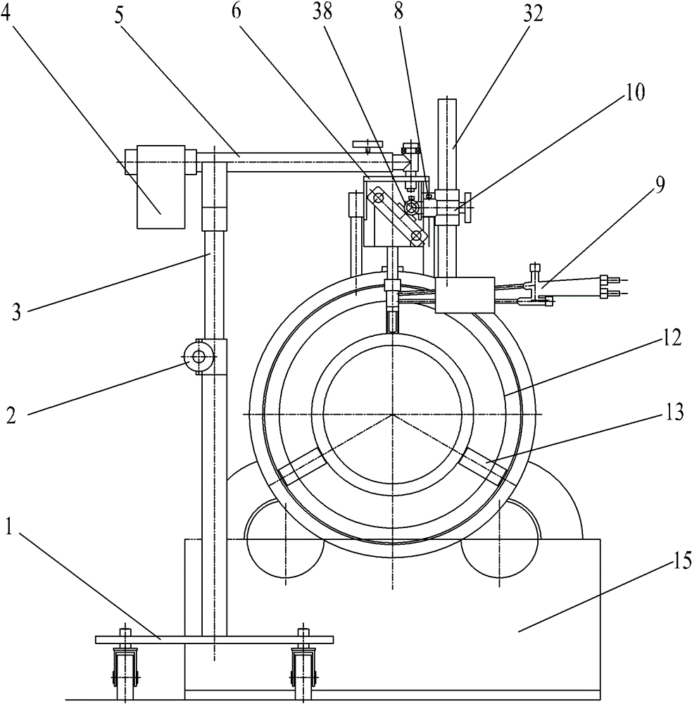
[0018] Such as Figure 1~Figure 3 As shown: the present invention includes a base 1, a lifting sleeve 2, a column 3, a balance weight 4, a cross arm 5, a hanger 6, a first positioning screw 7, a second positioning screw 8, a cutting torch 9, and a cutting torch adjustment sleeve 10 , Positioning sleeve 11, master mold 12, adjustment pad 13, overturning frame 14, driven wheel frame 15, driving wheel frame 16, column casing 17, bottom plate 18, casters 19, fixed pressure wheel 20, adjustment spring 21, inner tube Sleeve 22, inner tube set bolt 23, inner tube 24, pin shaft 25, bearing 26, slider 27, frame body 28, sliding shaft 29, movable pressure roller 30, compression bolt 31, auxiliary hanger 32, hinge Axle 33, workpiece 34, movable pinch roller connecting rod 35, fixed pinching roller connecting rod 36, connecting shaft 37 and hinged seat 38.

[0019] Such ...


PUM


Abstract

The invention relates to a saddle-shaped pipe end cutting device, comprising a roll-over stand and a base, wherein the base is provided with a stand column which is provided with a cross arm; end part of the cross arm is provided with a hanging bracket by a pin roll; the hanging bracket comprises a s bracket body which is provided with a slider shaft; the slide shaft is in slip connection with a slider which is provided with a regulating spring; the slider is provided with a cutting torch adjusting sleeve in a hinged mode, and the cutting torch adjusting sleeve is provided with a cutting torch; a fixed pinch roller and a movable pinch roller are arranged at the lower part of the bracket body; a locating sleeve is arranged between the movable pinch roller and the fixed pinch roller; the locating sleeve is provided with an explorator; the fixed pinch roller and the locating sleeve are in rolling contact opposite to the other side the side in which the explorator is arranged; and the movable pinch sleeve and the explorator are in rolling contact. The saddle-shaped pipe end cutting device of the invention has the advantages of compact structure, low processing cost and high processingprecision and is convenient to process and operate, is used for saddle-shaped pipe ends and cutting processing of beveled edges of the saddle-shaped pipe ends, and processing of parallel and level pipe ends and cutting processing of beveled edges of the flush pipe ends.

Description

technical field [0001] The invention relates to equipment for processing pipe ends, in particular to a saddle-shaped pipe end cutting device, which belongs to the technical field of pipe end cutting. Background technique [0002] As a common medium transportation channel, pipes are widely used in water supply, drainage, heat supply, gas supply, long-distance oil and gas transportation, agricultural irrigation, hydraulic engineering and various industrial installations, and steel pipes are especially common. The connection of pipelines mainly includes threaded connection, flange connection, socket connection and welding. Among them, welding connection has the best strength and sealing performance. It is suitable for various pipelines and saves labor and materials, but it must be cut off when disassembling. Tubes and tube couplings. It is unavoidable to use cross branch structure in the pipeline, and it is necessary to cut the intersecting line of the branch pipe ends of the ...

Claims


Application Information

Patent Timeline
Patent Type & Authority Patents(China)
IPC IPC(8): B23K7/00B23K7/10
Inventor 解胜飞
Owner WUXI HUAGUANG IND BOILER
Why Eureka
Try Eureka