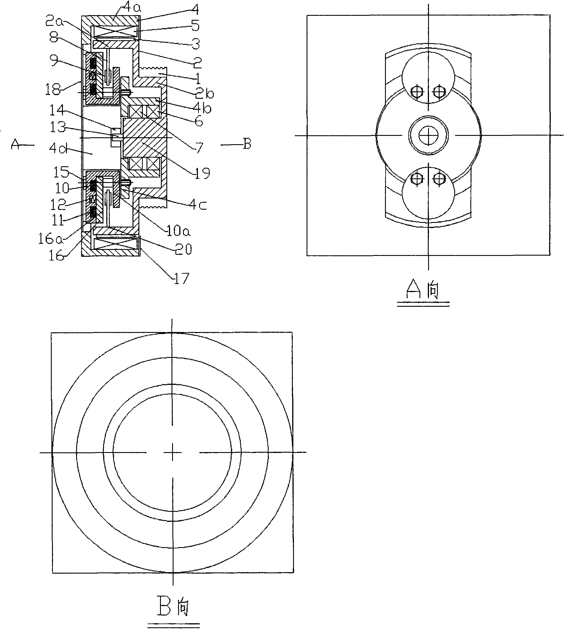
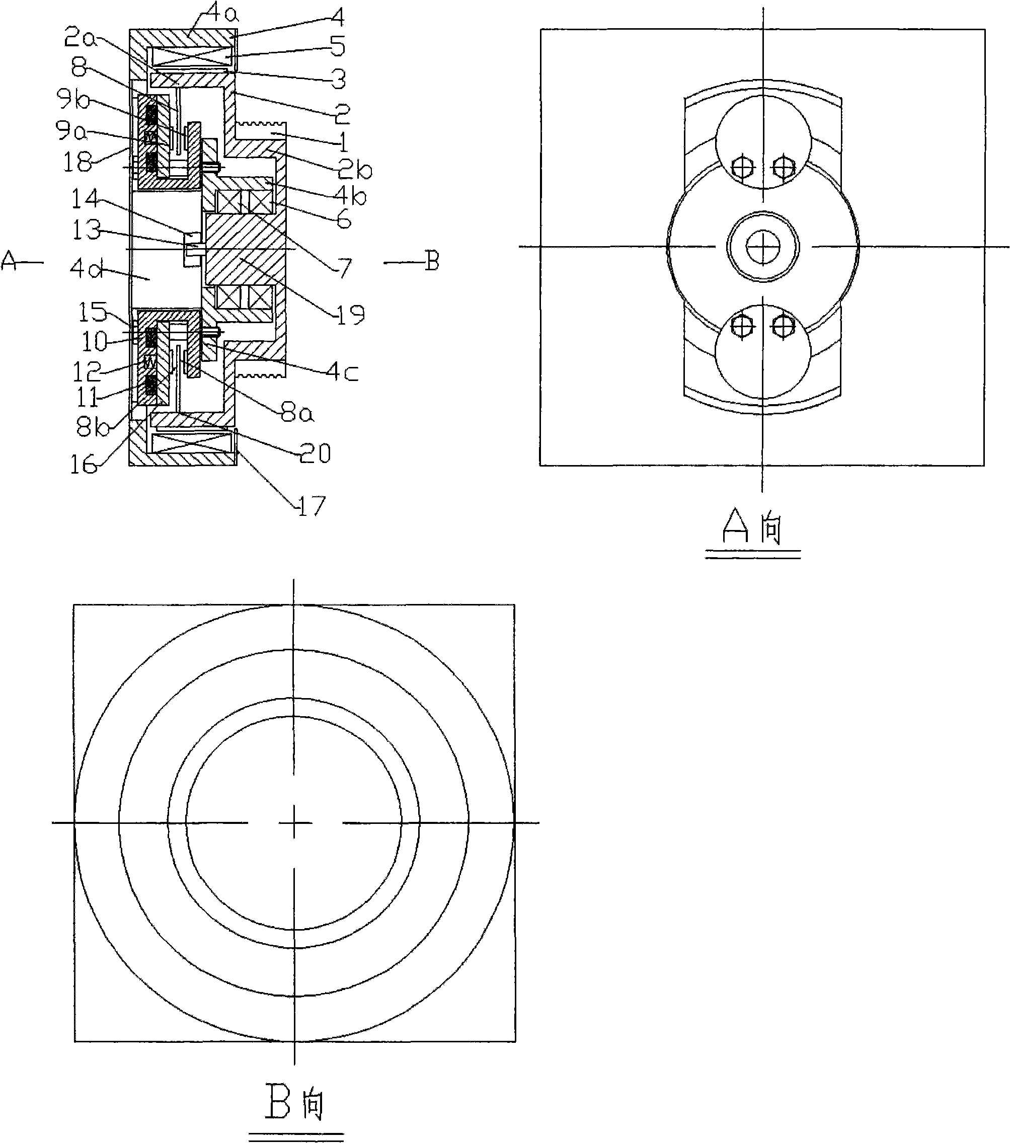
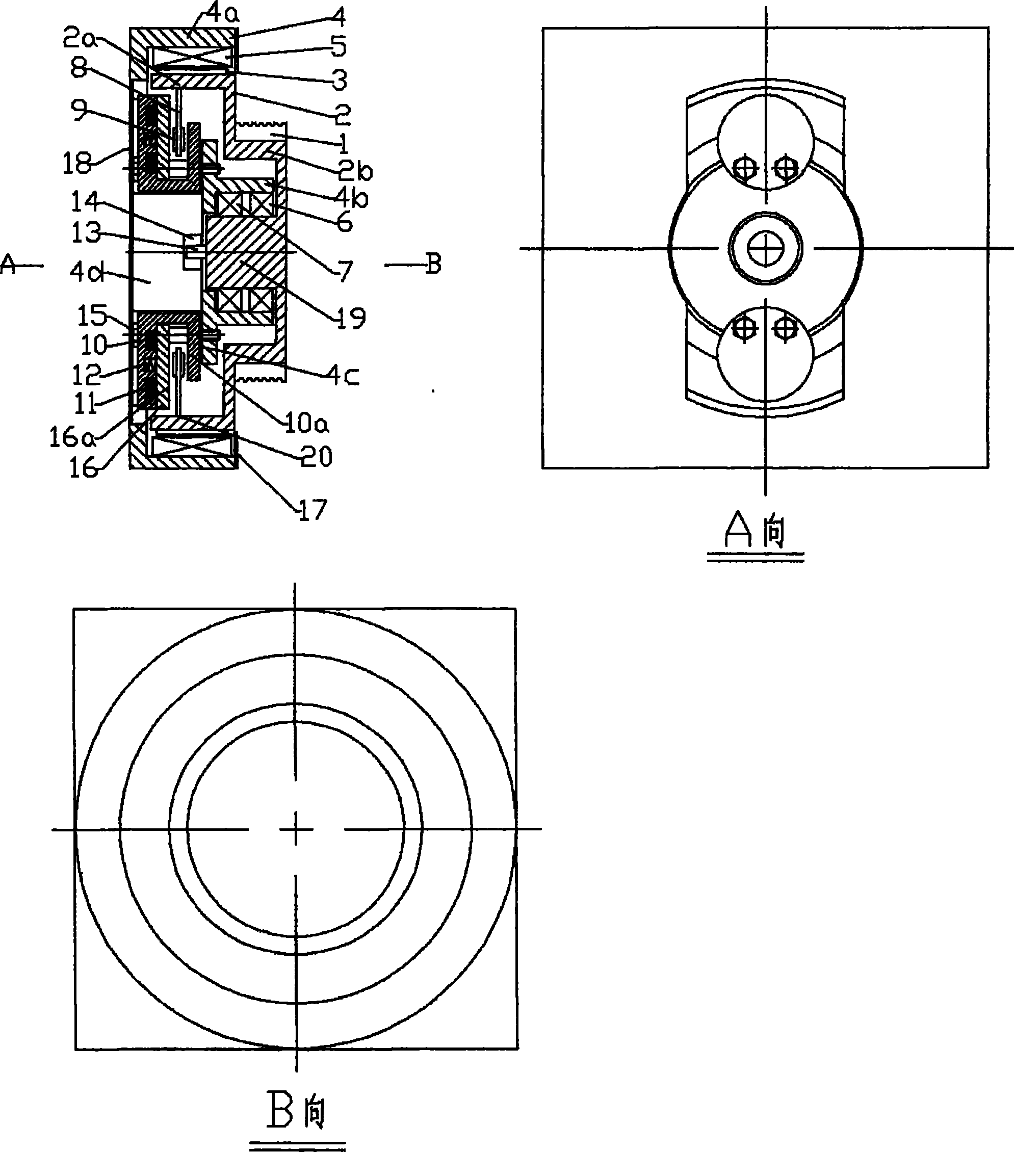
The disadvantages of this invention are: 1) because the brake wheel of the traction machine is located on the same side as the traction wheel and is arranged adjacently, the brake surface is very easily affected by the
grease of the steel
wire rope like this, thereby causing the
friction coefficient of the brake surface to decrease , the normal operation of the elevator has a catastrophic
impact; 2) Since the brake is set outside the traction machine, the
noise of the brake is directly transmitted outside, resulting in an increase in the
noise of the traction machine. The application in the elevator will directly affect the running quality of the elevator; 3) In order to reduce the noise, the gap between the friction plate and the brake wheel is usually set very small, so that when the brake arm acts on the brake wheel, due to The action time of the two brakes cannot be consistent, so it may cause the brake wheel to deform in the direction of the force, which may cause the other brake arm to contact the brake wheel, thus causing the friction plate of the other brake arm to wear. Reduce the service life of the brake arm, and may bring vibration and noise to the operation of the elevator; at the same time, in order to ensure that the brake wheel and the brake arm have sufficient rigidity, it is necessary to design a sufficiently strong brake arm and brake wheel, which will increase The cost of the traction machine, and because the
inertia of the brake wheel increases, the torque requirement of the traction machine is increased, thereby further increasing the cost of the traction machine; 4) Since the brake arm and the
electromagnet are arranged outside the traction machine, On the one hand, the outer dimension of the traction machine becomes larger, including the required axial dimension of the brake wheel and the height required by the
electromagnet, which affects the appearance of the traction machine. It is basically impossible for the traction machine to be applied to machine room-less elevator products. , on the other hand, the parts of the traction machine increase, the
processing amount of the parts increases, and the cost of the traction machine increases; 5) Since the magnetic steel is installed on the rotor, and the braking surface is also located on the rotor, the braking When the arm exerts a braking force on the brake wheel, it will have an
impact on the
magnet steel. Such impact will directly affect the connection between the
magnet steel and the rotor, which may cause the
magnet steel to fall off from the rotor, causing serious accidents and causing serious damage to the elevator. 6) Since the braking surface is the outer surface of the brake wheel, the braking force requirement is large, which is twice the braking force requirement of the end face (with two braking surfaces).
The weak point of this invention is: 1) in order to reduce noise, the gap between the braking shaft and the braking surface is usually arranged very little, so when the braking shaft acts on the braking surface, due to the two braking The dynamic action time cannot be consistent, so the rotor mounting part may be deformed in the direction of the force, which may cause another brake shaft to contact the braking surface, thereby causing the friction plate of the other brake shaft to wear and reduce the brake shaft. service life, and may bring vibration and noise to the operation of the elevator; at the same time, in order to ensure sufficient rigidity of the braking surface, it is necessary to design a sufficiently strong rotor mounting part, that is, the thickness of the rotor mounting part increases, which will increase the traction machine. cost, and because the
inertia of the rotor mounting part increases, the torque requirement of the traction machine is increased, thereby further increasing the cost of the traction machine; 2) In order to ensure a uniform gap between the braking shaft and the braking surface, the braking surface must Finishing, the cost of such
processing increases; 3) Since the friction plate of the brake shaft often has
wear debris, these
wear debris are likely to fall on the braking surface, which may cause the friction of the brake device to be unstable. The normal operation of the elevator has a serious impact, so it is necessary to regularly
clean up these
grinding debris, or use a
chip removal device to deal with these
grinding debris, which will increase the
workload of repair and maintenance, and increase the use cost of the traction machine; 4 ) Because the braking surface and the rotor mounting part are arranged on the rotating support frame oppositely, when the braking shaft generates braking force on the braking surface, it also produces an impact on the rotor, and such impact will directly affect the rotor and the rotating support frame The connection between the rotor mounting parts of the rotor will cause the rotor to fall off from the rotating support frame, thereby causing serious accidents and seriously affecting the operation of the elevator; 5) Since the braking surface is the inner circumferential surface of the rotor mounting part, the braking force The requirements are large, which is twice the braking force requirement of the brake device on the end face (with two braking surfaces), which increases the size and cost of the brake device and affects the structural size of the traction machine at the same time


