Continuous annealing furnace gas cleanliness detecting system

A continuous annealing furnace, furnace gas technology, applied in furnaces, heat treatment furnaces, furnace types, etc., to achieve the effect of reliable judgment basis

Inactive Publication Date: 2011-03-23
吕军 +1
View PDF3 Cites 4 Cited by
  • Summary
  • Abstract
  • Description
  • Claims
  • Application Information

AI Technical Summary

Problems solved by technology

[0005] The technical problem to be solved by the present invention is to provide a fast and reliable detection system for continuous annealing furnace gas pollutants in order to improve the quality of products such as middle and high-end automobiles and home appliance panels

Method used


Image

  • Continuous annealing furnace gas cleanliness detecting system
  • Continuous annealing furnace gas cleanliness detecting system
  • Continuous annealing furnace gas cleanliness detecting system

Examples


Embodiment 1

[0024] Example 1. Continuous annealing furnace atmosphere cleanliness detection system

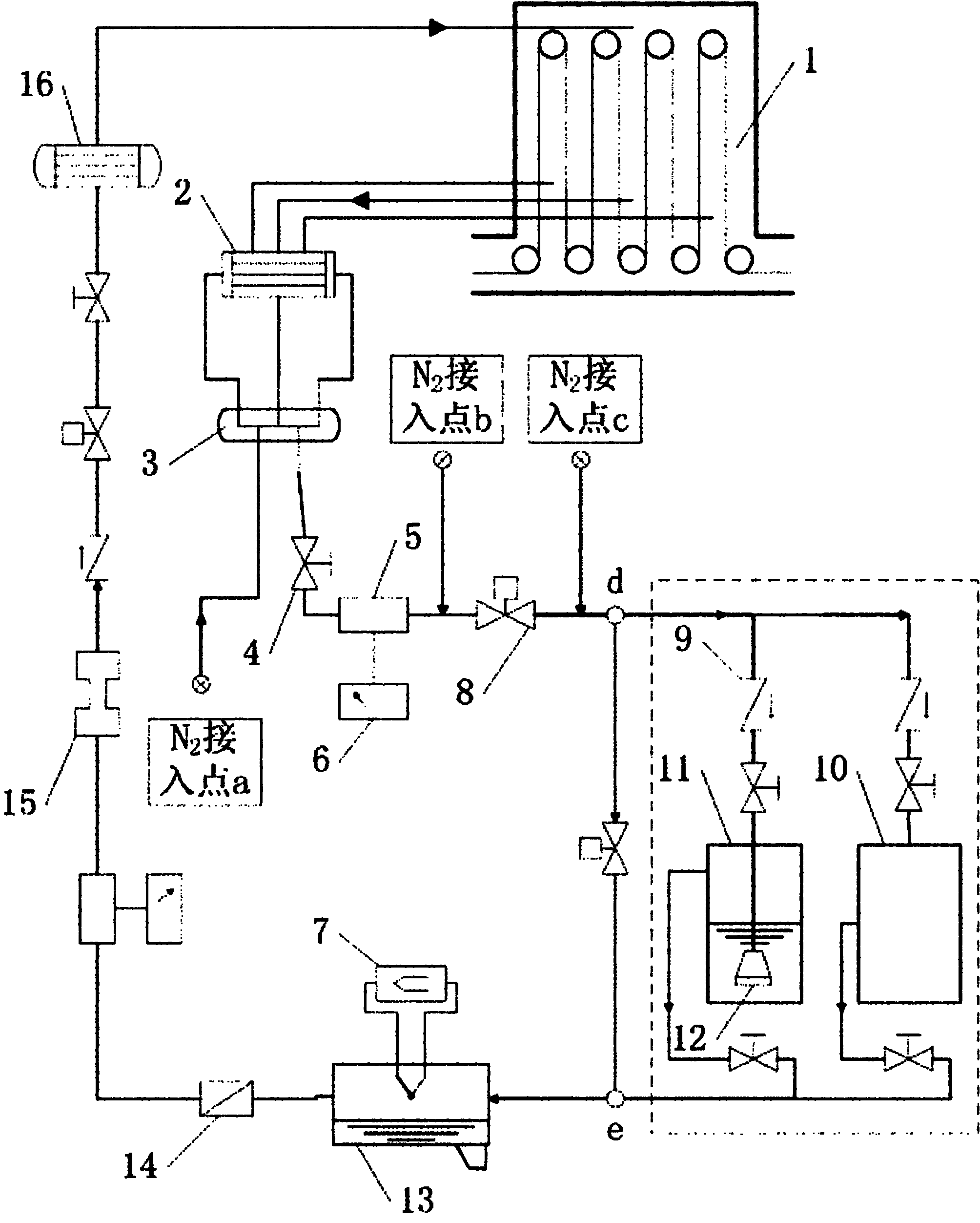
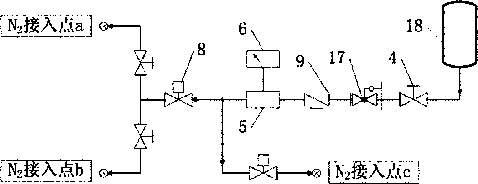
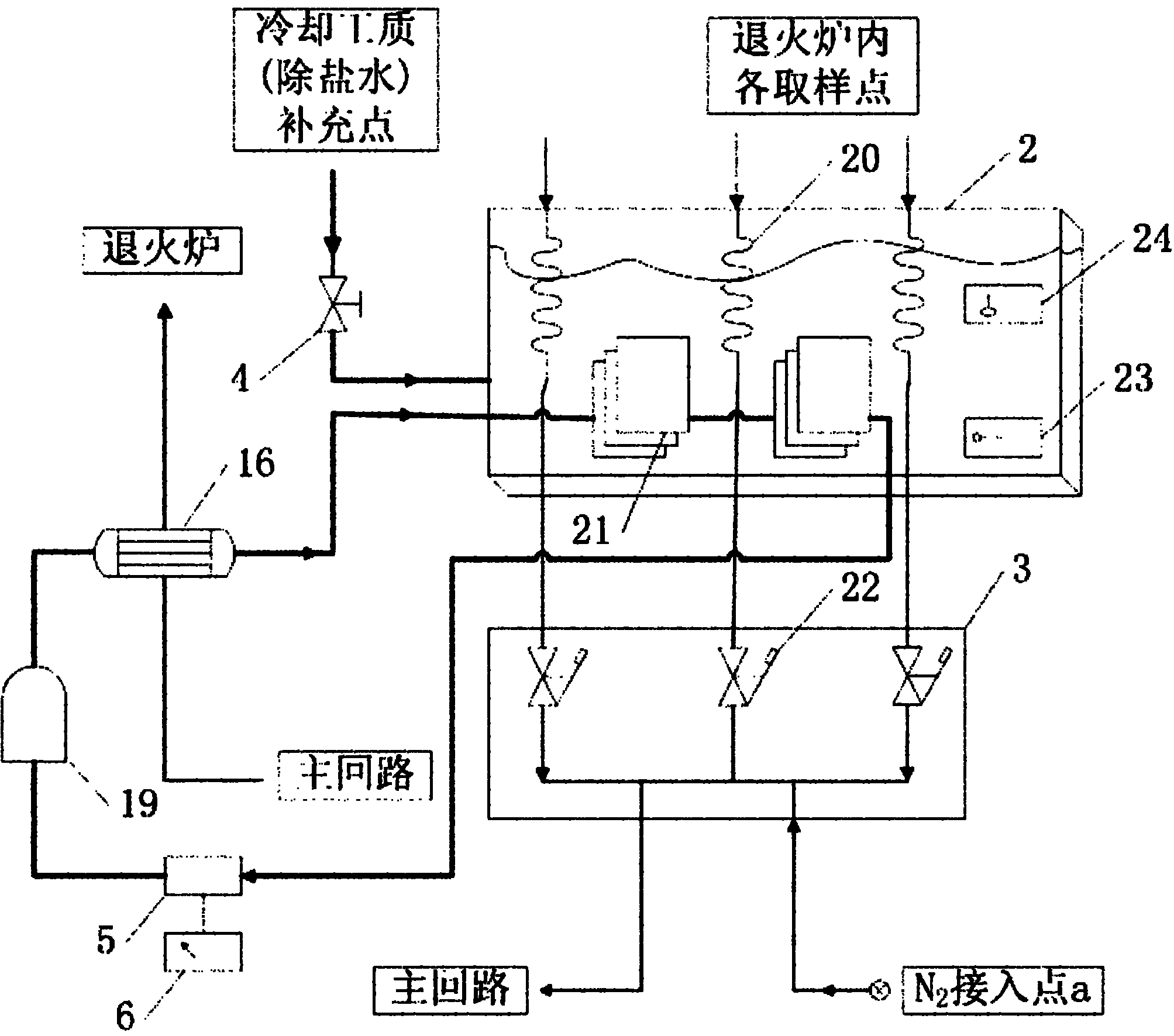
[0025] The detection system for atmosphere cleanliness in a continuous annealing furnace provided by the present invention is mainly composed of a furnace gas sampling supervisor, a gas pollutant collector branch, and a metering and gas return supervisor. Wherein: the furnace gas sampling main pipe, its input end communicates with the annealing furnace chamber 1 through a pipeline, its output end is connected with the input end of the gas pollutant total collector branch through a pipeline, and is connected with the nitrogen purge circuit connected to the output. The output end of the gas pollutant collector branch is connected with the input end of the metering and gas return main pipe through a pipeline. The input end of the nitrogen purge circuit is connected to the nitrogen station through a pipeline; the nitrogen purge circuit is connected in parallel to the gas distributor 3 of the ...

Embodiment 2

[0054] Example 2. Application of the detection system for the cleanliness of the atmosphere in the continuous annealing furnace

[0055] The detection system provided by the present invention can be used for manual detection of the cleanliness of the atmosphere in the continuous annealing furnace in the field of medium and high-end automobile or household appliance panel production. The detection system is based on the following detection methods, specifically: Use a sampling metering pump to pump out the gas in the furnace chamber of the annealing furnace, and make the furnace gas pass through the collector according to the set flow rate, and various particles in the furnace gas will be blocked in the collector The sampling metering pump will automatically measure the volume of the collected furnace gas, and the controller will send the temperature and pressure signals measured by the instrument in front of the sampling metering pump to the computer for processing, so that the...


PUM


Abstract

The invention discloses a continuous annealing furnace gas cleanliness detecting system, which mainly comprises a furnace gas sampling master pipe, a gas pollutant collector branch and a metering and gas return master pipe, wherein the input end of the furnace gas sampling master pipe is communicated with the interior of an annealing furnace chamber through a pipeline, and the output end of the furnace gas sampling master pipe is connected with the input end of the gas pollutant gross collector branch through a pipeline and connected with the output end of a nitrogen blowing loop; the output end of the gas pollutant collector branch is connected with the input end of the metering and gas return master pipe through a pipeline; and the input end of the nitrogen blowing loop is communicated with a nitrogen station through a pipeline, the nitrogen blowing loop is connected in parallel on the pipelines of a gas distributor and an automatic switching valve of the furnace gas sampling master pipe through two manual switching valves connected in series with the nitrogen blowing loop, and the output end of the metering and gas return master pipe is communicated with the interior of the annealing furnace chamber through a pipeline. The system can accurately detect pollutants in the furnace in time, and provides basis for improving product quality, reasonably arranging shutdown maintenance and clearing the furnace.

Description

technical field [0001] The invention relates to the technical field of heat treatment of cold-rolled metal strips, in particular to a gas cleanliness detection system in a continuous annealing furnace, which is used in the production fields of medium and high-end automobiles and home appliance panels. Background technique [0002] With the increasing demand for high surface quality products in the automobile and home appliance industries, the requirements for product surface quality are becoming more and more stringent, which promotes the development of new technologies for continuous galvanizing and continuous annealing production lines. However, the continuous annealing furnace as the core equipment is subject to high temperature, Affected by factors such as airtightness, some key issues that restrict the improvement of product quality have not been broken through. The detection of the cleanliness of the gas in the furnace under the production state of the continuous anneal...

Claims


Application Information

Patent Timeline
Patent Type & Authority Applications(China)
IPC IPC(8): C21D9/56G01N1/22
Inventor 吕军郑剑辉廖慧
Owner 吕军
Why Eureka
Try Eureka