Unbalanced shaft

A balanced shaft, balanced technology, applied in the field of unbalanced shafts, can solve the problems of no lubricant inlet, wear of rolling contacts, etc.

Inactive Publication Date: 2011-03-23
SCHAEFFLER TECH AG & CO KG
View PDF7 Cites 9 Cited by
  • Summary
  • Abstract
  • Description
  • Claims
  • Application Information

AI Technical Summary

Problems solved by technology

However, in the case of the publication cited at the outset, there is concern about insufficient lubrication of the rolling contacts between the rolling elements and the inner raceway leading to wear, since it concerns a completely closed inner raceway and in Insufficient lubricant inlet inside the rolling bearing

Method used


Image

  • Unbalanced shaft
  • Unbalanced shaft
  • Unbalanced shaft

Examples


Embodiment Construction

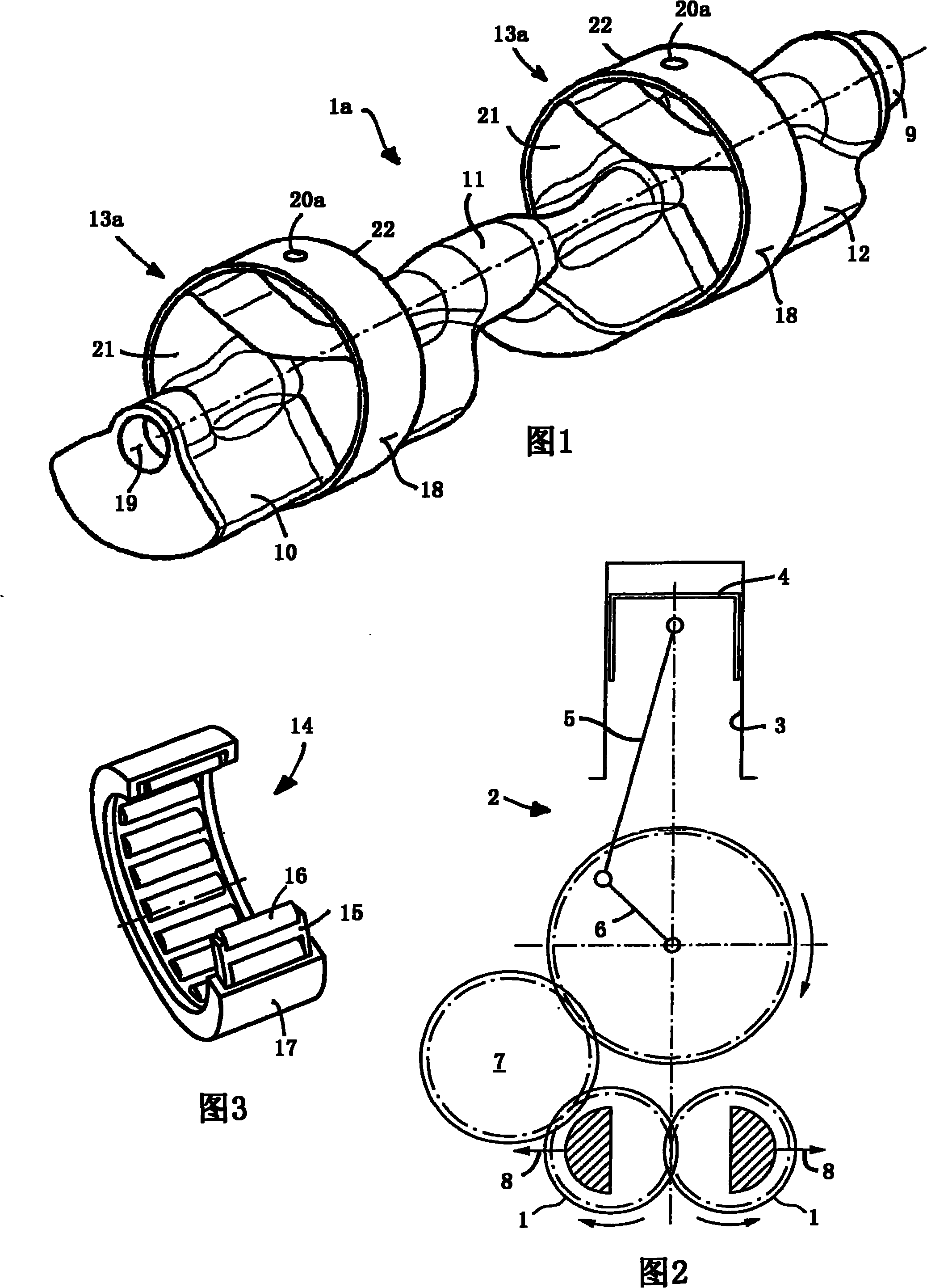
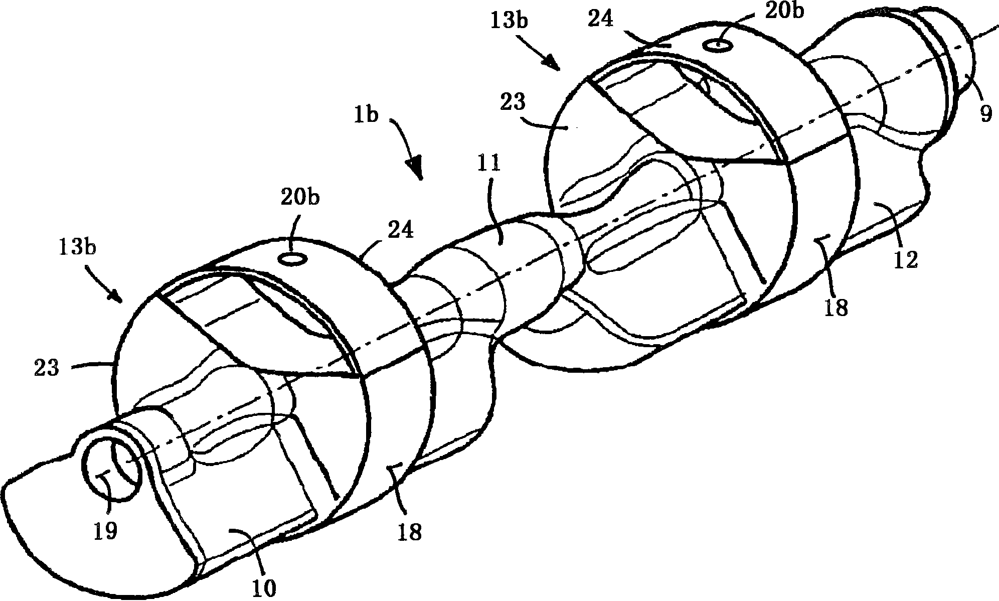
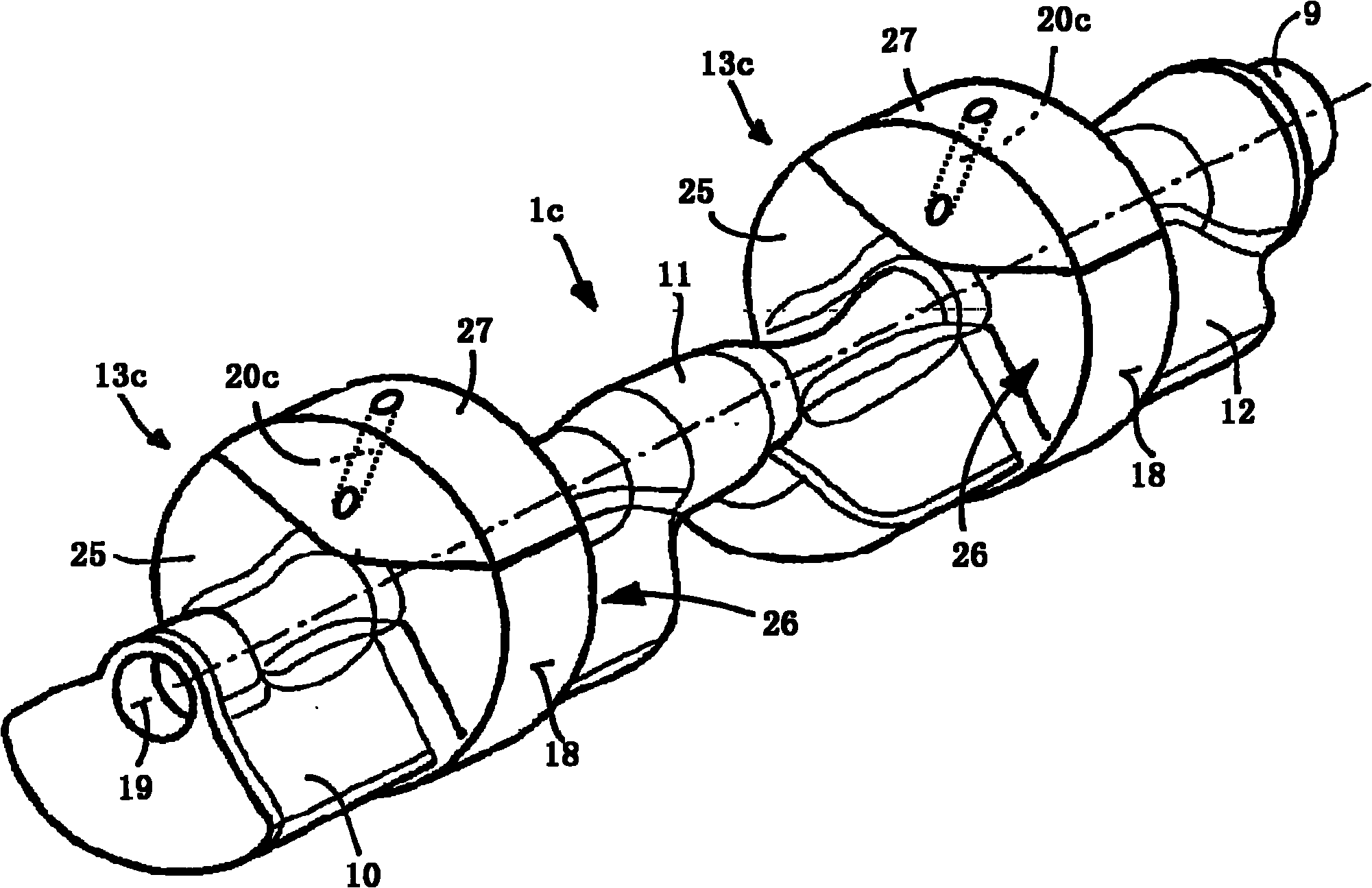
[0016] exist figure 1 , 4 Shown in and 5 is the unbalance shaft 1, which is used to balance the second-order inertial forces of a piston internal combustion engine in a four-cylinder in-line configuration (Vierzylinder-Reihenbauweise). This mass-balance transmission, also known as Lancaster balance (Lancaster-Ausgleich), is produced by figure 2 It is known from the schematic diagram of the transmission shown in . Internal combustion engine 2 includes four pistons 4 oscillating in cylinders 3 , the longitudinal movement of which is converted into rotation of a crankshaft 6 via connecting rods 5 . This drives (here via the intermediate shaft 7 ) the two unbalance shafts 1 with unbalance bodies 8 , wherein the unbalance shafts 1 rotate parallel to the crankshaft 6 in opposite directions at double the crankshaft speed.

[0017] The unbalanced shaft 1 , which is driven on the drive section 9 , for example via sprockets or gears not shown, comprises three shaft sections 10 , 11 ...


PUM


Abstract

An unbalanced shaft (1a, 1b, 1c), particularly for compensating mass forces and / or mass moments of inertia of an internal combustion engine (2) is provided. The shaft includes a shaft section (10, 11, 12) and a bearing journal (13a, 13b, 13c) axially adjacent to the shaft section, the bearing journal includes a fully cylindrical outer peripheral surface (18) serving as an inner raceway for the rolling elements (16) of a rolling bearing (14) and the bearing journal has a multi-piece configuration, so that both the shaft section and the bearing journal possess a mass center of gravity that, for producing the shaft unbalance, extends eccentric to the axis of rotation (19) of the unbalanced shaft. For supplying lubricant to the inner raceway and the rolling elements, an oil channel (20a, 20b, 20c) extends radially outwards through the bearing journal and opens, relative to the mass center of gravity of the bearing journal, on the other side, situated beyond the axis of rotation, on the outer peripheral surface.

Description

technical field [0001] The invention relates to an unbalanced shaft having a shaft section and a journal adjacent to the shaft section in the axial direction, the journal having a full cylindrical shape as an inner raceway for the rolling bodies of a rolling bearing The outer shell is also multi-part in that the center of mass of both the shaft section and the journal is distributed eccentrically with respect to the axis of rotation of the unbalanced shaft in order to generate a shaft unbalance. The unbalance shaft serves in particular to balance the inertial forces and / or moments of inertia of the internal combustion engine. Background technique [0002] Unbalanced shafts according to the classification are known from DE 10 2007 009 800 A1 and DE 10 2007 027 990 A1. A considerable weight reduction of the unbalanced shaft is achieved in each case in that both the shaft section and the journal contribute to the generation of the shaft unbalance. For this purpose, the journa...

Claims


Application Information

Patent Timeline
Patent Type & Authority Applications(China)
IPC IPC(8): F16F15/26
CPCF16F15/267F16F2230/04F16C19/46F16C33/588F16C33/60F16C33/62F16C33/6677F16C2208/00F16C2240/30F16C2361/53Y10T74/2183
Inventor 彼得·索尔弗兰克
Owner SCHAEFFLER TECH AG & CO KG
Why Eureka
Try Eureka