
Phase-line and neutral-line type residual current action breaker

A residual current and circuit breaker technology, applied in the field of residual current circuit breakers, can solve the problems of reduced arc-extinguishing space, reduced arc-extinguishing capacity, and no fundamental solution in phase circuits, and achieves simple electrical connection process and reduced power loss. , the effect of simple structure

Active Publication Date: 2011-03-23
ZHEJIANG CHINT ELECTRIC CO LTD
View PDF3 Cites 18 Cited by
  • Summary
  • Abstract
  • Description
  • Claims
  • Application Information

AI Technical Summary

Problems solved by technology

[0006] In the circuit breaker with the above structure, the neutral circuit is installed at the pole of the circuit breaker, the phase circuit is installed between the neutral circuit and the leakage protection pole, and the passage of the inner conductor of the neutral circuit is in the In the space of the phase circuit, on the one hand, it makes the electrical connection between the neutral line circuit and the leakage protection pole difficult; The arc extinguishing space is reduced, the arc extinguishing ability is reduced, and the product is unreliable when breaking under high short-circuit current conditions
[0007] Improved structure, such as Chinese patent ZL200820118766.X "Auxiliary release mechanism for circuit breaker", in which the neutral circuit and phase circuit are set on the same side, Therefore, the above-mentioned problems have not been fundamentally solved.
[0008] In addition, such as the EDE-C40 and C40-DM residual current operated circuit breakers produced by ** Company, although the neutral circuit and the leakage tripping device are set at one pole, the closing and disconnection of the neutral circuit is controlled by another including the operating handle. It is completed by a four-bar linkage mechanism, with many parts and complex structure

Method used


Image

  • Phase-line and neutral-line type residual current action breaker
  • Phase-line and neutral-line type residual current action breaker
  • Phase-line and neutral-line type residual current action breaker

Examples


Embodiment Construction

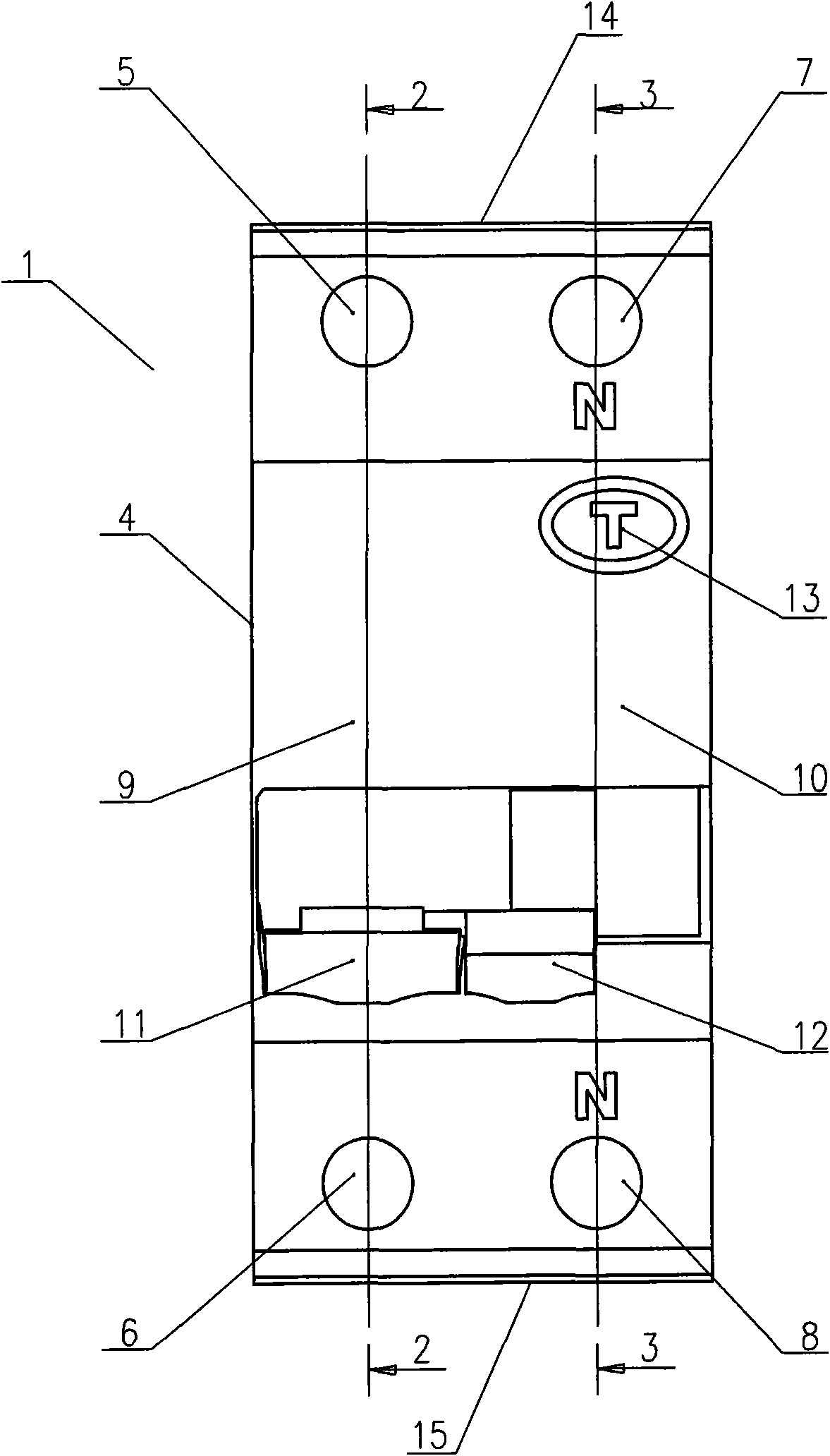
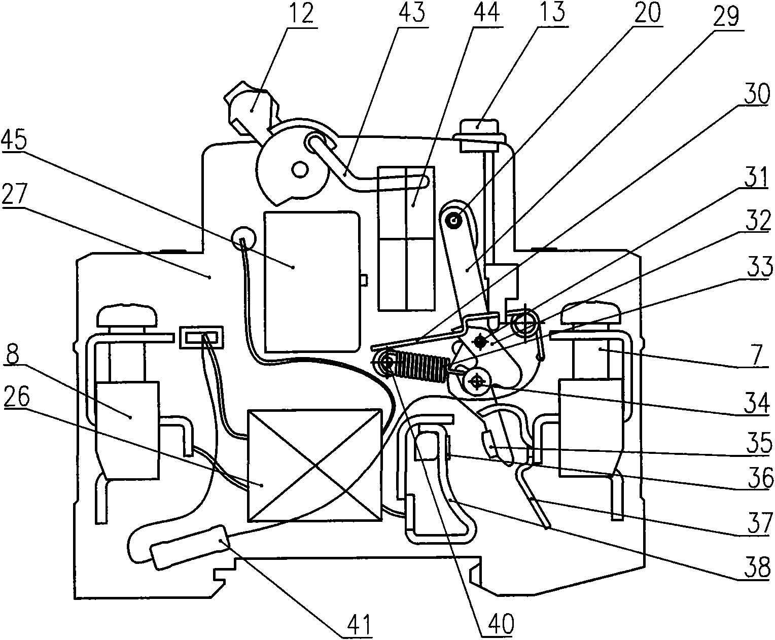
[0026] refer to Figure 1 to Figure 4 , the phase line plus neutral line type residual current operated circuit breaker 1 of the present invention is installed in an insulating shell 4, and the shell is subdivided into two adjacent parts by the middle partition plate 27, the first part is the circuit breaker phase pole, the second The second part is the leakage protection pole.

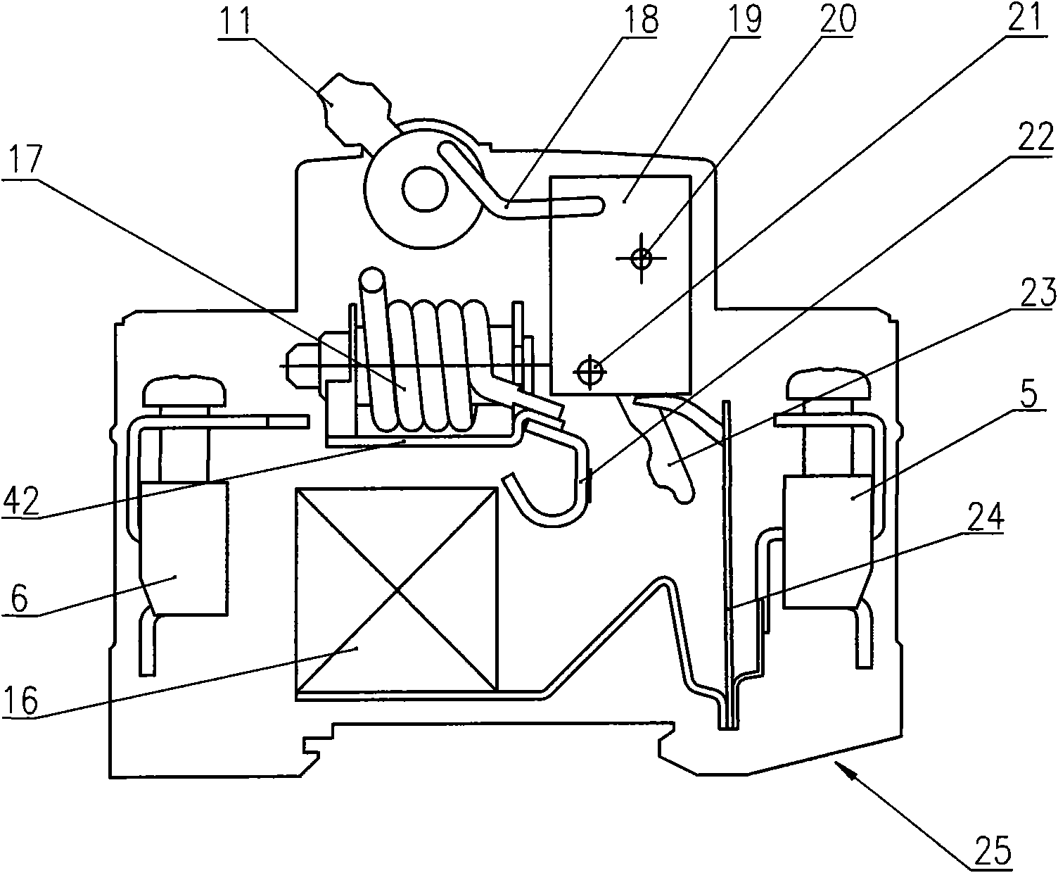
[0027] refer to figure 2 , The first part 9 of the circuit breaker includes a phase circuit 25 and a pair of phase terminals 5, 6 connected thereto. The upstream terminal 5 is provided on one narrow side 14 of the housing 4 and the downstream terminal 6 is provided on the other opposite surface 15 . The phase circuit 25 includes a moving contact 23, which is electrically connected with the upstream terminal 5 by the bimetal release 24; also includes a static contact connected to the front end of the excitation coil 17 of the electromagnetic release 42 22; and a phase pole primary winding comprisin...


PUM


Abstract

The invention discloses a phase-line and neutral-line type residual current action breaker, which comprises an insulating shell. The insulating shell is divided into two adjacent parts by a clapboard and comprises a breaker phase pole of the first part and a leakage protection pole of the second part. The invention is mainly characterized in that a neutral-line circuit and a leakage protection device are arranged in the same plane, and the on and the off of a movable contact of a neutral pole are controlled by a phase pole operation mechanism, therefore, the electric connection process is simple, the length of a neutral line electric loop is shortened, the operation power loss of the product is reduced and the structure is more reasonable. Meanwhile, the movable contact of the neutral pole is mechanically coupled with the phase pole operation mechanism through a drive rod, so that the movable contact of the phase pole and the movable contact of the neutral pole are cooperatively acted, and the movable contact of the neutral pole is closed first and then cut off with simple structure.

Description

technical field [0001] The invention relates to a residual current operated circuit breaker (GB16917.1-2002), in particular to a phase line plus neutral line type residual current operated circuit breaker with overcurrent protection. In IPC, it belongs to H01H 83 / 00 (protective switch that operates not only in overcurrent, but also in various abnormal electrical conditions, such as circuit breaker or protective relay), H01H 83 / 02 (operated by ground fault current Two or more unbalanced currents or voltages, such as differential protection, H01H 83 / 14 priority), H01H 71 / 00 (zero of protective switches or relays included in each group of H01H73 / 00 to H01H 83 / 00 Parts) and H01H 71 / 02 (housing; housing; base; bracket; H01H 71 / 10? Operating or releasing mechanism). Background technique [0002] Existing phase line plus neutral type residual current operated circuit breaker with overcurrent protection, such as European patent EP0456585 "unipolar plus neutral type residual current...

Claims


Application Information

Patent Timeline
IPC IPC(8): H01H83/14H01H71/40
Inventor 周长青于利英
Owner ZHEJIANG CHINT ELECTRIC CO LTD
Learn More