Thermoelectric module and optical transmission apparatus

A thermoelectric module and thermoelectric conversion technology, applied in the direction of circuits, electrical components, electrical solid devices, etc., can solve the problems of slow heat conduction, long distance, and inability to maintain the temperature of the laser diode at the specified temperature, so as to simplify wire bonding and improve reliability. Excellent performance and responsiveness

Inactive Publication Date: 2012-10-10
AISIN SEIKI KK
View PDF1 Cites 1 Cited by
  • Summary
  • Abstract
  • Description
  • Claims
  • Application Information

AI Technical Summary

Problems solved by technology

Therefore, the distance from the heat generated by the thermoelectric conversion element to the fixed surface (21b) for heat dissipation becomes longer, and the heat conduction is slow.
In addition, compared with the first opposite surface (21a), the area of ​​the fixed surface (21b) is limited due to the component specifications of the optical transmission device, and the area of ​​the fixed surface cannot be larger.
As a result, sufficient heat dissipation cannot be performed from the fixed surface (21b)
When operating the laser diode (40) provided on the second insulating substrate side, there is a problem that the temperature of the laser diode (40) cannot be kept at a predetermined temperature with high precision.

Method used


Image

  • Thermoelectric module and optical transmission apparatus
  • Thermoelectric module and optical transmission apparatus
  • Thermoelectric module and optical transmission apparatus

Examples


Embodiment 1

[0035] figure 1 A thermoelectric module 2 according to Embodiment 1 of the present invention is schematically shown. figure 2 is an explanatory diagram schematically showing the state of manufacturing the thermoelectric module 2 of Example 1, Figure 5 An optical transmission device 1 incorporating a thermoelectric module 2 is schematically shown.

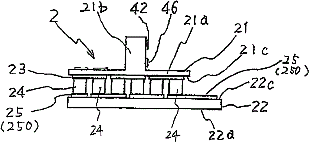
[0036] Such as figure 1 As shown, the thermoelectric module 2 has a first insulating substrate 21 , a second insulating substrate 22 , a plurality of electrodes for thermoelectric conversion elements (hereinafter referred to as electrodes) 23 and 25 , and a plurality of thermoelectric conversion elements 24 .

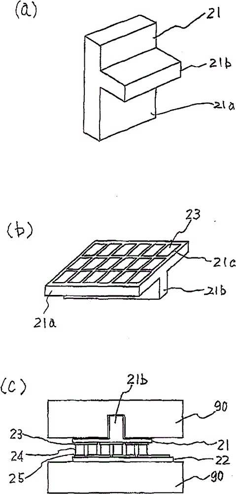
[0037] The first insulating substrate 21 is made of alumina, such as figure 1 The cross-section shown is convex, and the first insulating substrate 21 has a substrate main body portion 21a and a convex portion 21b. The substrate main body portion 21a has a long plate shape. The convex part 21b is connected to the cente...

Embodiment 2

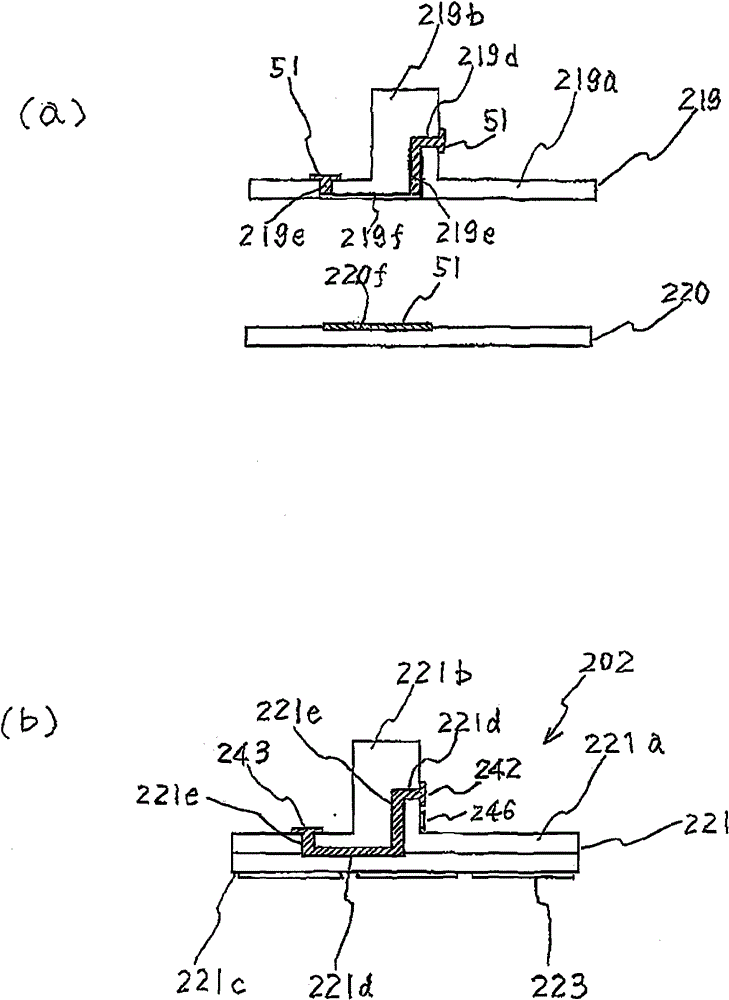
[0044] Next, refer to image 3 , the thermoelectric module 202 in which the first insulating substrate has two layers is described. In addition, in Embodiment 2, the integration process of the first insulating substrate 21 and the second insulating substrate 22 and the structure of the second insulating substrate are the same as those of Embodiment 1, so the description is omitted, and only the structure different from that of Embodiment 1 will be described. the first insulating substrate.

[0045] Such as image 3 As shown in (a), the alumina mixed material in the form of slurry is prepared, and the first insulating substrate intermediate molded product 219 and the flat plate-shaped first insulating substrate intermediate molded product 220 are formed respectively. Afterwards, on the first insulating substrate intermediate molded product 219, the horizontal conduction circuit hole 219d, the vertical conduction circuit hole 219e, and the horizontal conduction circuit hole gr...

Embodiment 3

[0048] Next, refer to Figure 4 , illustrating the thermoelectric module 302 . in addition, Figure 4 The structure shown is in image 3 In terms of structure, the thermistor 344 is mounted on the convex portion 319b, the integration process of the first insulating substrate and the second insulating substrate and the structure of the second insulating substrate are the same as those of the first embodiment, so the description is omitted, and only the same as that of the first embodiment is described. 1 different first insulating substrates.

[0049] Such as Figure 4 As shown in (a), the alumina mixed material in the form of slurry is prepared, and the first insulating substrate intermediate molded product 319 having a substantially square-shaped cross section and the first insulating substrate intermediate molded product 320 having a flat plate shape are respectively molded. Afterwards, the horizontal conductive circuit hole 319d, the vertical conductive circuit hole 319...


PUM


Abstract

To provide a thermoelectric module that can be arranged in a limited space and is excellent in heat exchange capability, and to provide an optical transmitter comprising the same. A first insulating substrate (21) comprises the following components: a substrate body (21a) with a first opposite surface (21c); and a protruding part (21b) which is integrally formed with the substrate body (21a) on an opposite surface that is at the opposite side of the first opposite surface (21c) and is opposite with an area provided with an electrode. The protruding part (21b) is provided with a thermoelectricconversion element (24) and a connection part (42) connected with a cooled object. The heat generated by the cooled object is efficiently transferred from the protruding part (21b) to a second insulating substrate (22) with the thermoelectric conversion element (24).

Description

technical field [0001] The present invention relates to a thermoelectric module with a thermoelectric conversion element and an optical transmission device with the thermoelectric module. Background technique [0002] The thermoelectric module cools the device using a thermoelectric conversion element (for example, a Peltier element), and various thermoelectric modules have been known conventionally. For example, the thermoelectric module for an optical transmission device disclosed in Patent Document 1 discloses a thermoelectric module (2), which includes: a first insulating substrate (21) having a first opposite surface (21a); The second insulating substrate (22) on the opposite second opposing surface (22c); a plurality of electrodes (23, 25) formed on the first opposing surface and the second opposing surface respectively; A plurality of thermoelectric conversion elements (24) electrically connected in series or parallel to the electrodes between the substrates; and a c...

Claims


Application Information

Patent Timeline
Patent Type & Authority Patents(China)
IPC IPC(8): H01L25/04H01L25/16H01L23/498H01L23/38H01L25/075
CPCH01L2224/49111
Inventor 森本晃弘
Owner AISIN SEIKI KK
Why Eureka
Try Eureka