
Demodulator and method capable of automatically calibrating output and television receiver thereof

A TV receiver and demodulator technology, applied in the field of receivers, can solve the problems of signal transmission errors, receiver system 1 noise interference circuit area, and inability to miniaturize, etc.

Active Publication Date: 2011-03-23
MEDIATEK INC
View PDF4 Cites 13 Cited by
  • Summary
  • Abstract
  • Description
  • Claims
  • Application Information

AI Technical Summary

Problems solved by technology

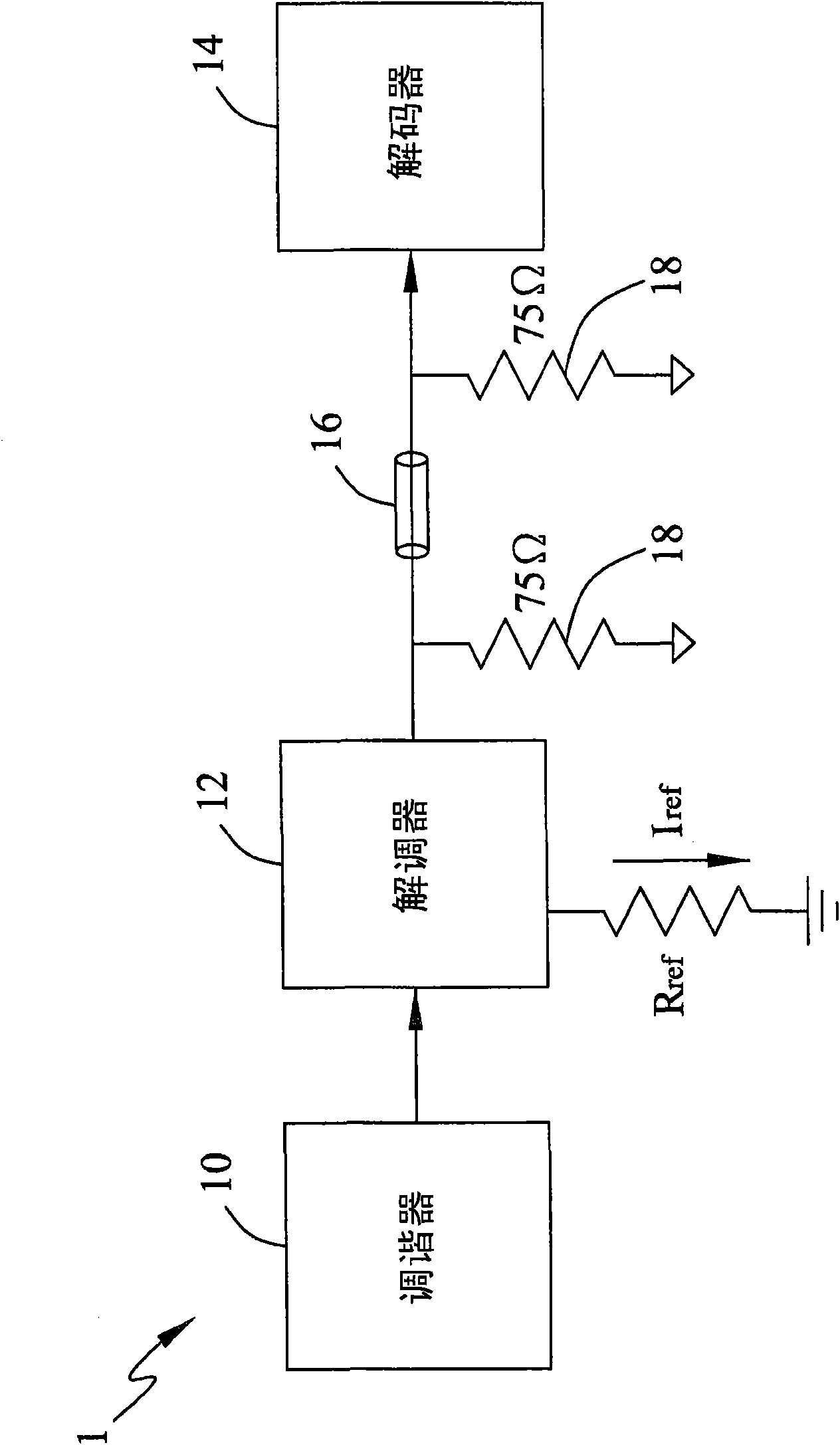
[0003] Since the demodulator 12 and the decoder 14 are fabricated on separate printed circuit boards, the receiver system 1 is susceptible to noise interference and the circuit area cannot be miniaturized
Furthermore, even if the precision resistor 18 is used, the output voltage swing of the demodulator 12 still has considerable The deviation value (variation), may cause errors in signal transmission

Method used


Image

  • Demodulator and method capable of automatically calibrating output and television receiver thereof
  • Demodulator and method capable of automatically calibrating output and television receiver thereof
  • Demodulator and method capable of automatically calibrating output and television receiver thereof

Examples


Embodiment Construction

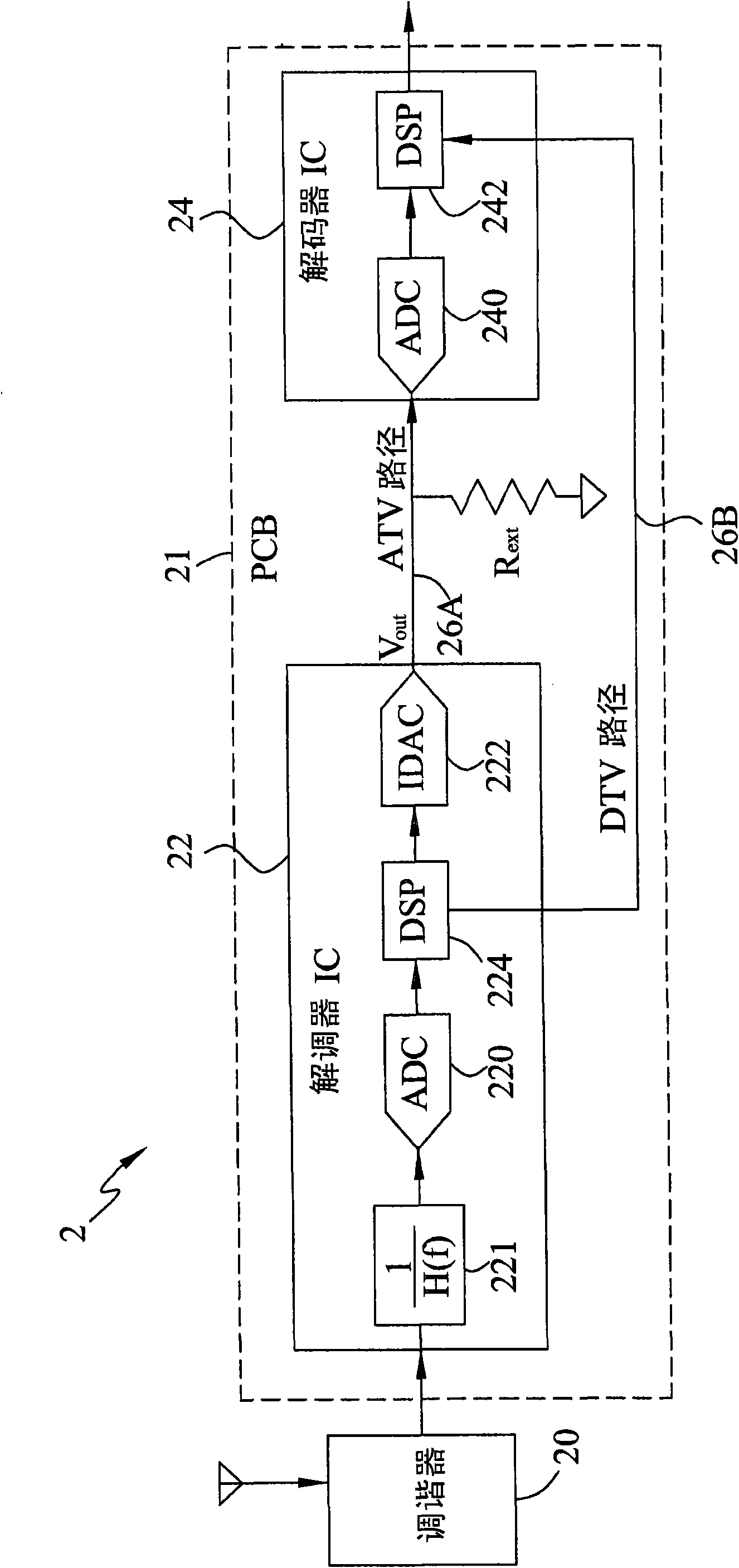
[0015] figure 2 A system block showing a digital / analog television receiver of one of the embodiments of the present invention figure 2 , which mainly includes a tuner (tuner) 20 , a demodulator (demodulator) 22 and a decoder (decoder) 24 . Although the receiver 2 of this embodiment can receive and process both digital and analog TV signals, the present invention is also applicable to only receive and process digital TV signals or only analog TV signals.

[0016] The tuner 20 is used to match the impedance of an antenna or a cable (not shown) and tune the radio frequency signal down to a base frequency signal. Next, the demodulator 22 demodulates the received TV signal to extract the TV signal V from the modulated carrier wave. out . The decoder 24 then performs decoding so as to display the TV signal on a screen (not shown). Such as figure 2 As shown, the demodulator 22 of this embodiment includes a filter 221 , an analog-to-digital converter (ADC) 220 , a digital sig...


PUM


Abstract

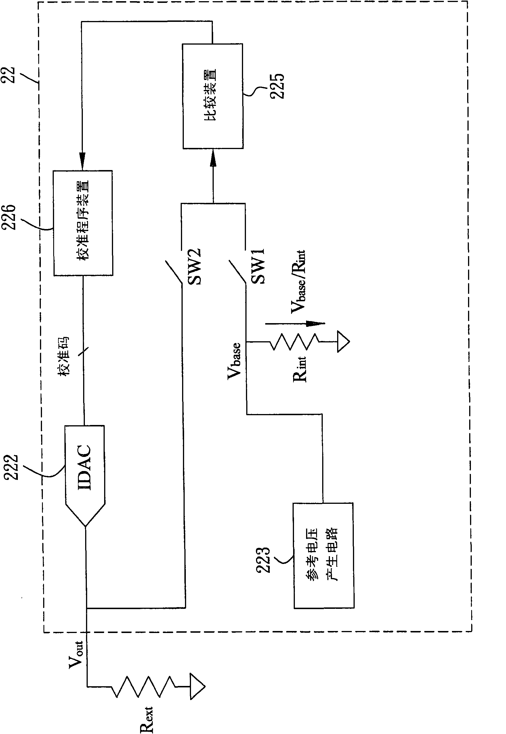
The invention discloses a television demodulator and a method capable of automatically calibrating output and a television receiver thereof. The television demodulator comprises a reference voltage generating circuit, a reference resistor, a current type digital-to-analog converter, a comparison device and a calibration program device. The reference voltage generating circuit generates a reference voltage; the reference resistor is used for converting the reference voltage to provide a reference current; the current type digital-to-analog converter receives a digital code and generates an output signal; the comparison device compares the reference voltage with the output signal to generate a comparison output; and the calibration program device updates the digital code according to the comparison output to calibrate the current type digital-to-analog converter.

Description

technical field [0001] The present invention relates to a digital / analog television receiver, in particular to a power-saving and self-calibrating demodulator with current-mode digital-to-analog converter (IDAC), method and television receiver thereof. Background technique [0002] In recent years, countries all over the world are gradually popularizing the broadcasting and reception of digital TV (DTV), thus forming the coexistence of digital TV and traditional analog TV (ATV). figure 1 A system block diagram of a traditional digital / analog TV receiver 1 is shown, which mainly includes a tuner 10 , a demodulator 12 and a decoder 14 . The demodulator 12 and the decoder 14 of the conventional receiver 1 are fabricated on separate printed circuit boards (PCBs), and a coaxial cable 16 is used to transmit signals between the two circuit boards. Since the impedance of the general coaxial cable is 75 ohms (Ω), in order to allow the impedance of the receiver 1 to be matched, two c...

Claims


Application Information

Patent Timeline
Patent Type & Authority Applications(China)
IPC IPC(8): H04N5/44H04N5/455
Inventor 魏骏恺林永欣
Owner MEDIATEK INC
Learn More