Spinning machine with suction apparatus and method for controlling suction apparatus of spinning machine

A suction device, a technology for textile machines, applied in spinning machines, textiles and papermaking, transportation and packaging, etc., can solve problems such as large share, achieve low energy consumption, reliable suction, and optimize the effect of suction effect

Active Publication Date: 2011-03-30
RIETER INGOLSTADT GMBH
View PDF12 Cites 13 Cited by
  • Summary
  • Abstract
  • Description
  • Claims
  • Application Information

AI Technical Summary

Problems solved by technology

[0005] Although the method described already contributes to the energy-efficient operation of certain textile machines, there is a need for further energy savings, especially since the suction device accounts for a large share of the total energy consumption of the textile machine

Method used


Image

  • Spinning machine with suction apparatus and method for controlling suction apparatus of spinning machine
  • Spinning machine with suction apparatus and method for controlling suction apparatus of spinning machine

Examples


Embodiment Construction

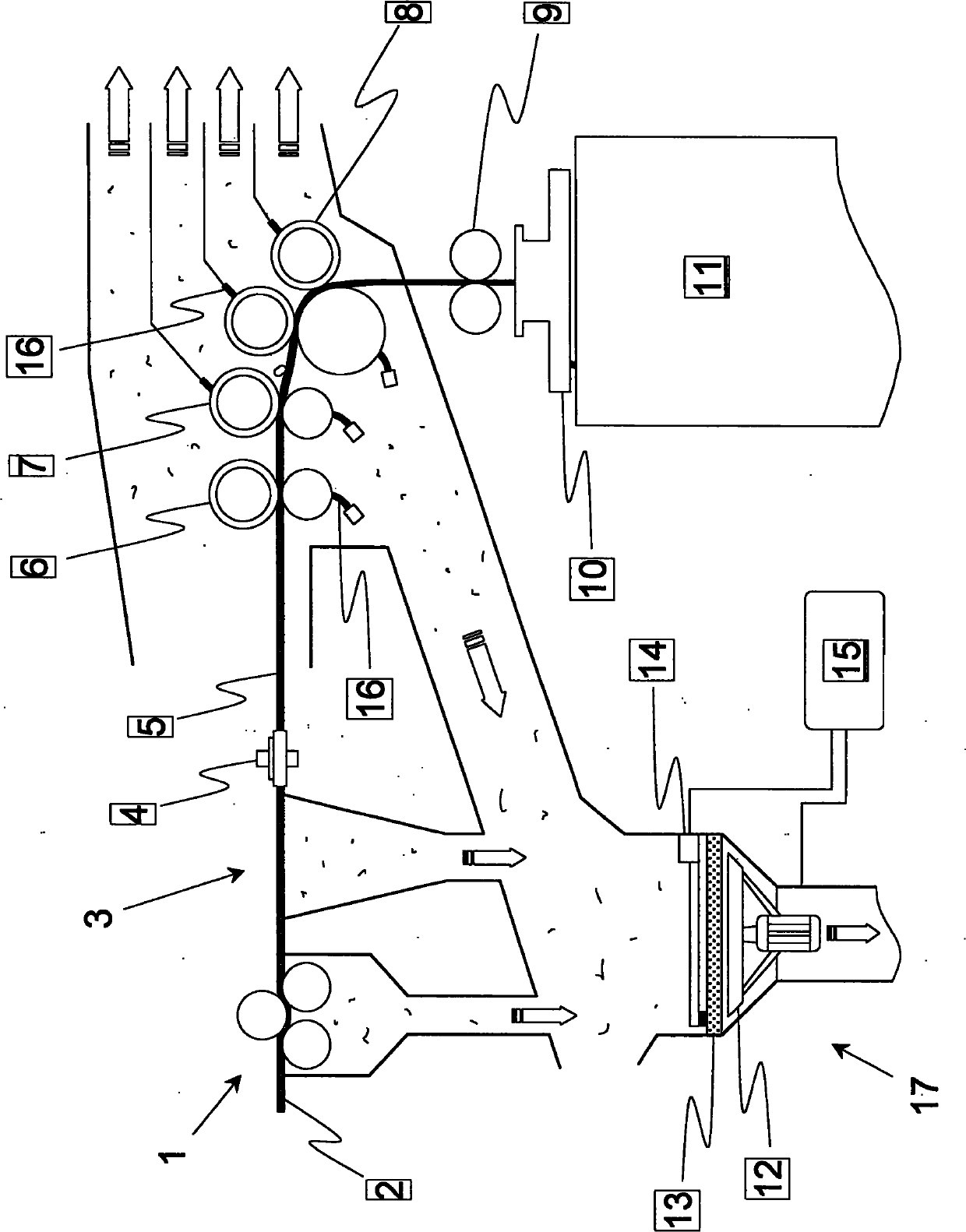
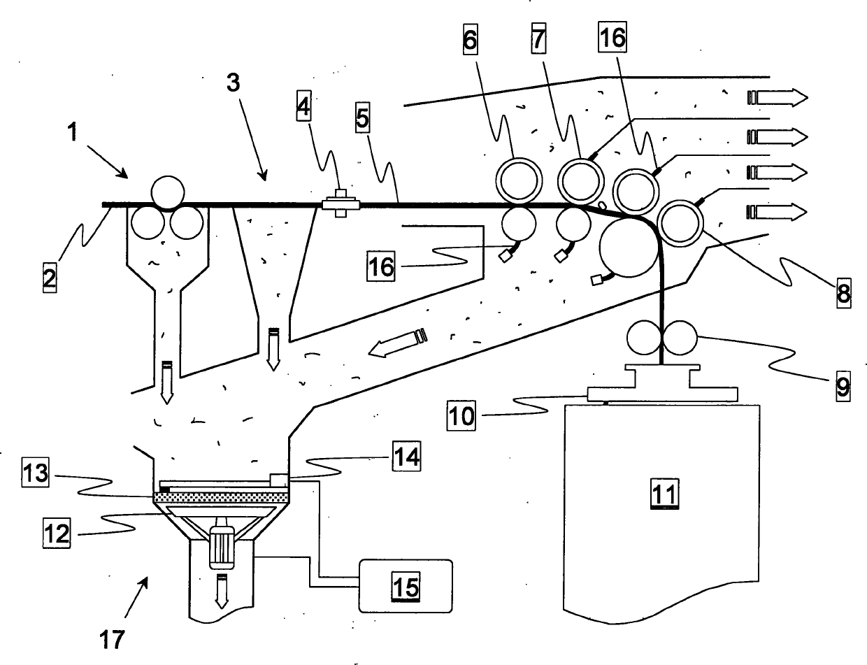
[0049] exist figure 1 The textile machine in the form of a mill according to the invention shown in has in principle an entry area with a corresponding single-stand rolling mill 1 from which a plurality of fibers to be stretched is withdrawn from the (not shown) tank bundle 2. The parallel fiber bundles are then introduced across the corresponding feed table 3 with suction gaps running perpendicularly to the plane of the sheet and finally brought together to form a fiber strand 5 by a first pair of rollers 4, wherein this pair of rollers 4 is also used at the same time. as a measuring device to detect possible thickness fluctuations of the fiber bundle 2 and to take care of the subsequent delay through the roller compactor.

[0050] The calender itself also has an entry roll pair 6 , an intermediate roll pair 7 and an exit or feed roll arrangement 8 , which rotate at successively increasing peripheral speeds in that order. In the calender, the fiber strands 5 are processed f...


PUM


Abstract

The present invention relates to a method for controlling a suction apparatus of a spinning machine, particularly a spinning or spinning preparing machine, e.g. a rubbing mill, a napping machine or a combing machine, wherein the suction apparatus (17) includes a ventilator (12) for generating air flow, a filter element (13) for filtering the air flow and a cleaning device for cleaning the filter element (13). According to the invention, rotational speed of the ventilator and an operating status of the cleaning device are coordinated by a controller (15). Furthermore, the invention describes a corresponding spinning machine having the suction apparatus (17), wherein the suction apparatus includes a ventilator (12) for generating air flow, a filter element (13) for filtering the air flow and a cleaning device for cleaning the filter element (13). The spinning machine is characterized in that the ventilator (12) and the cleaning device (14) is connected with the controller (15) of the spinning machine, such that the rotational speed of the ventilator and the operating status of the cleaning device are coordinated.

Description

technical field [0001] The invention relates to a method for controlling a suction device of a textile machine, in particular a spinning or spinning preparation machine, such as a roller compactor, a napping machine or a combing machine, wherein the suction device comprises a fan, a filter element for filtering the airflow and a cleaning device for cleaning the filter element. Furthermore, a textile machine with a corresponding suction device is proposed, in particular a spinning or spinning preparation machine, such as a roller compactor, a napping machine or a combing machine. Background technique [0002] Suction devices can be incorporated into various textile machines and are used there to remove dust, lint or other grime substances that accumulate during the processing of fibrous materials. For this purpose, an airflow is usually generated in the area of ​​the dirt-sensitive plant parts, wherein the corresponding suction channels are connected to individual fans or, h...

Claims


Application Information

Patent Timeline
Patent Type & Authority Applications(China)
IPC IPC(8): D01H5/66B65H54/88
CPCB65H54/88D01H5/66
Inventor 米夏埃尔·施特罗贝尔阿尔贝特·克里格勒米夏埃尔·于丁
Owner RIETER INGOLSTADT GMBH
Why Eureka
Try Eureka