Blind in hollow glass

A louver and glass technology, applied in the field of louvers, can solve the problems of incomplete overturning of the counterweight bottom beam 20, poor shading performance, shading coefficient and thermal insulation performance of hollow louver glass, etc., and achieve good energy-saving performance, high shading performance, and turning over smooth effect

Inactive Publication Date: 2011-03-30
常熟欧泰克建筑节能科技有限公司
View PDF4 Cites 6 Cited by
  • Summary
  • Abstract
  • Description
  • Claims
  • Application Information

AI Technical Summary

Problems solved by technology

like Figure 1C As shown, the overturning of the counterweight bottom beam 20 is not complete, so the shieldi

Method used


Image

  • Blind in hollow glass
  • Blind in hollow glass
  • Blind in hollow glass

Examples


Embodiment Construction

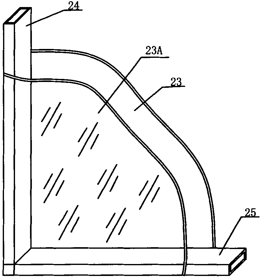
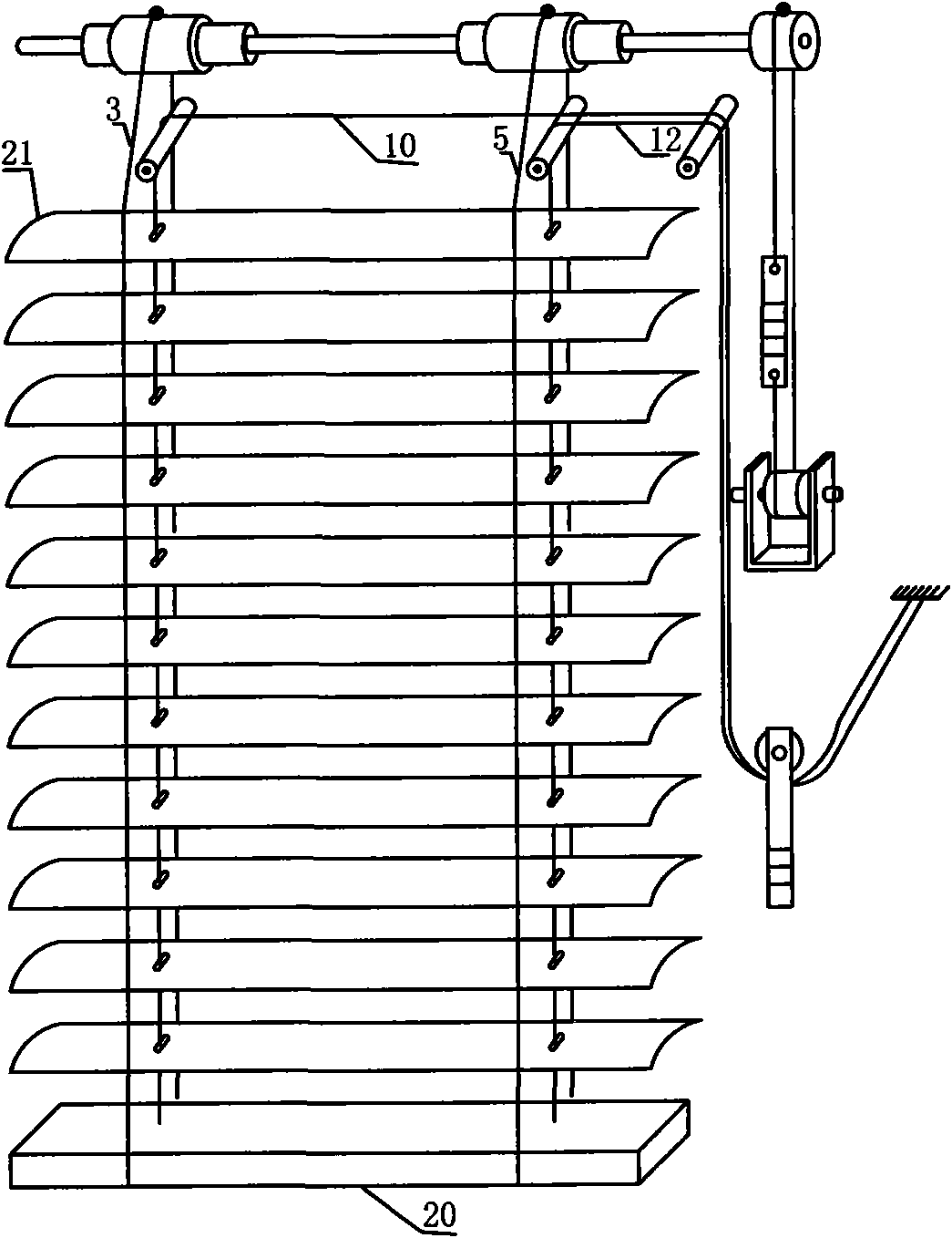
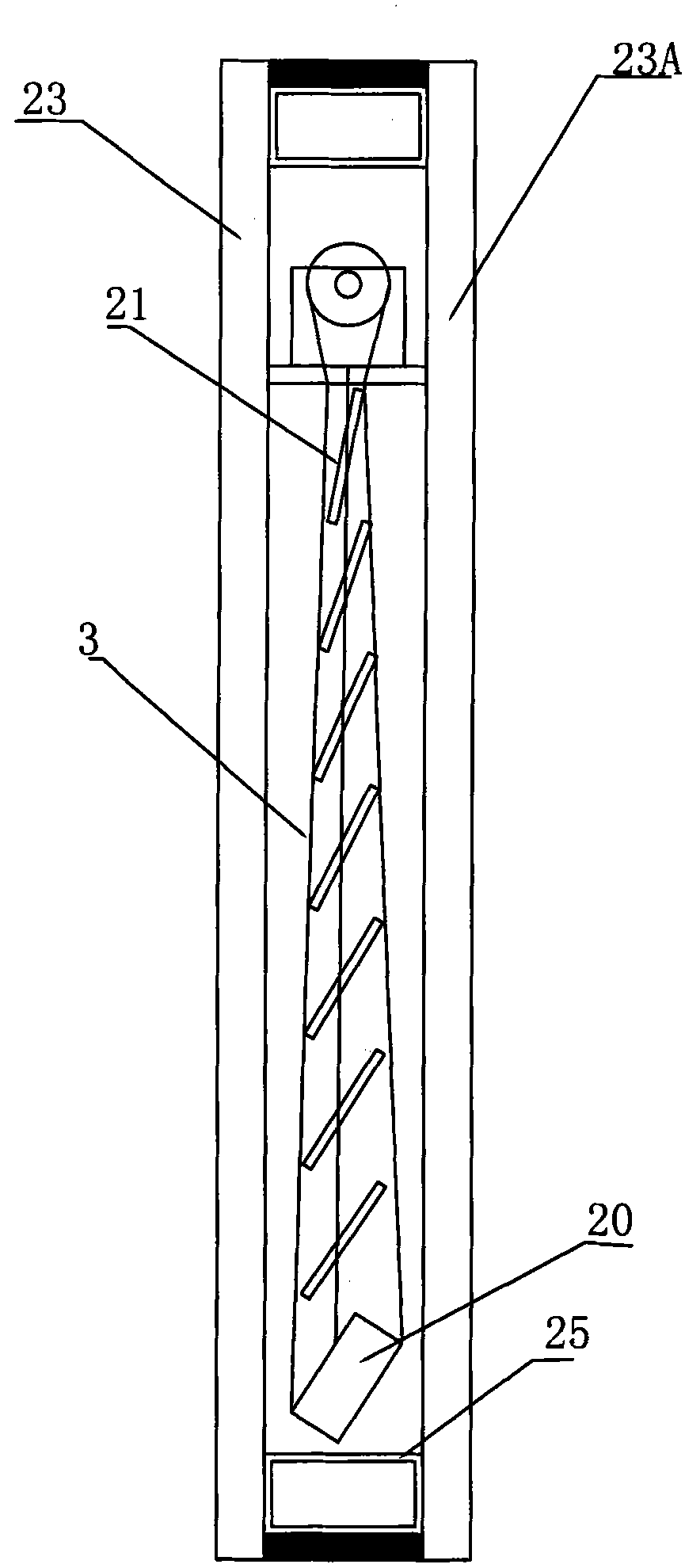
[0020] Figure 2A It is a schematic diagram of the structure of an embodiment of the present invention, and only shows the part of the blinds in the hollow glass. The figure shows the blinds installed in the hollow glass in the space enclosed by the outdoor side glass 23, the indoor side glass 23A and the frame 24. The structure of outdoor side glass 23, indoor side glass 23A and frame 24 see Figure 1A The present invention does not change these structures. See again Figure 2A The upper and lower long shafts 1 of the shutter body are respectively fixed on the frame 24, and each long shaft 1 is provided with a set of coaxial friction wheels 2, 4. The steering ropes 3 and 5 are connected to each other head and tail respectively, and are respectively wound on the upper and lower friction wheels 2, 4 and fixed, and are fixed to the two long sides of each blade 21 at the front and rear to form two closed rope sets. . The upper and lower steering wheels 6 are respectively arranged...


PUM


Abstract

The invention discloses a blind in hollow glass. The upper part and the lower part of the blind are both provided with blind turning control structures; the upper part and the lower part of the blind are turned simultaneously during blind turning, and the blind turning degrees of the upper part and the lower part are the same, thereby improving the shielding performance, the shading coefficient, the thermal insulation property and the total energy saving performance of the hollow blind glass.

Description

Technical field [0001] The invention relates to a shutter, in particular to a shutter in hollow glass. Background technique [0002] For the needs of environmental protection, energy saving and comfortable life, sunshade products are widely used by people. On indoor windows, blinds (curtains) and folding curtains are more common. Due to its unique heat insulation, sound insulation, anti-condensation, anti-dust and pollution characteristics, hollow glass has been widely used all over the world after more than one hundred years of development. The applicant of the present invention has previously applied for a number of patents such as ZL03238471.8 (US patent of the same family US7124803B2), ZL200320128533.5 and ZL200420057384.2, all of which are related to the blinds built in hollow glass, which belong to one of the hollow glass built-in sun-shading products. [0003] Figure 1A , Figure 1B It is a schematic diagram of the utility model patent "Blinds in Insulating Glass" (patent ...

Claims


Application Information

Patent Timeline
IPC IPC(8): E06B9/264E06B9/32E06B3/66
Inventor 金仁哲
Owner 常熟欧泰克建筑节能科技有限公司
Why Eureka
Try Eureka