Continuously variable valve timing phaser

A valve timing and phaser technology, which is applied in the direction of machines/engines, engine components, mechanical equipment, etc., can solve problems such as insufficient fuel combustion, difficult control of control mechanisms, heavy pollution, etc., to improve power and fuel economy , Improve torque and power, and fully burn gasoline

Inactive Publication Date: 2011-03-30
成都恒高机械电子有限公司
View PDF7 Cites 8 Cited by
  • Summary
  • Abstract
  • Description
  • Claims
  • Application Information

AI Technical Summary

Problems solved by technology

[0004] In order to improve the intake and exhaust efficiency, the opening time of the intake valve and the exhaust valve has a certain overlap, but due to the change of the engine speed, the overlap time required is different, and the previous engine cannot take into account the high speed state and the low speed state. The optimal opening and closing timing of the state valve, there is currently no reliable device to achieve the optimal opening and closing timing of the valve. In addition, when the valve overlap occurs in the intake process, the incoming fuel will be burned after incomplete combustion. Exhaust, the existing design is to design the oil passage on the cam, which makes it difficult to control the control mechanism from the position of the maximum delay to the position of advance, and it is difficult for the engine to realize the automatic adjustment of the camshaft under different conditions, and the fuel combustion is not sufficient , and heavy pollution

Method used


Image

  • Continuously variable valve timing phaser
  • Continuously variable valve timing phaser
  • Continuously variable valve timing phaser

Examples


Embodiment Construction

[0020] The present invention will be further described below in conjunction with the accompanying drawings, but the scope of protection is not limited to the description.

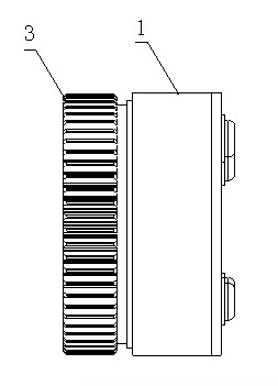
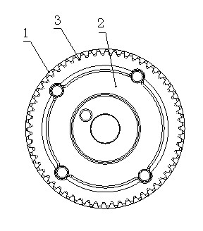
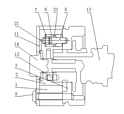
[0021] Such as figure 1 , figure 2 , image 3 , Figure 4 , a continuously variable valve timing phaser, which is fixed on the camshaft 13 through pins 12 and mounting bolts 14, which includes a casing 1, an impeller 2, a sprocket 3, screws 9, a rear cover 11, a locking mechanism 18, The sealing assembly 19 and the locking mechanism 18 are pressed into the impeller 2 to form the impeller assembly. The impeller assembly is placed in the casing 1. The two ends of the casing 1 are sealed with the back cover 11 and the sprocket 3. The screw 9 passes through the back cover 11 and the casing 1 and then screwed. The sprocket 3 fixes the back cover 11, the impeller 2 is free to rotate in the closed space formed by the casing 1, the back cover 11 and the sprocket 3, grooves 25 are distributed on the casing 1 and...


PUM


Abstract

The invention discloses a continuously variable valve timing phaser. The phaser is arranged on a camshaft (13) and comprises a shell (1), an impeller (2), a chain wheel (3), a screw (9), a back cover (11), a locking mechanism (18) and a sealing component (19), wherein the impeller (2) rotates freely in an enclosed space formed by the shell (1), the back cover (11) and the chain wheel (3); the locking mechanism (18) is arranged in the impeller (2); grooves (25) are distributed on the shell (1) and the impeller (2); and the sealing component (19) is arranged in the groove (25) and partitions a relatively sealed space between the shell (1) and the impeller (2) into an advance cavity (15) and a lag cavity (16). The phaser has the advantages that: the phase position of the camshaft is adjusted automatically according to different working conditions, and the opening and closing of an intake valve and an exhaust valve are changed along with the change of rotating speed, so that the aim of improving dynamic property and fuel economy is fulfilled.

Description

technical field [0001] The invention relates to the technical field of engines, in particular to a continuously variable valve timing phaser. Background technique [0002] In recent decades, based on the requirements of improving the power, economy and reducing pollution of automobile engines, many countries, engine manufacturers and scientific research institutions have invested a lot of manpower and material resources in the research and development of new technologies. According to the working principle of the engine, in order to To achieve a complete combustion state, it is necessary to inhale as much fresh air as possible and exhaust exhaust gas as much as possible. At present, the best solution is to open the intake valve in advance and delay the closing of the exhaust valve. At present, variable valve timing (VVT) technology has been used in It has been applied in internal combustion engines, but it is still in the stage of development and perfection. It may becom...

Claims


Application Information

Patent Timeline
Patent Type & Authority Applications(China)
IPC IPC(8): F01L1/34
Inventor 汪澜范国平
Owner 成都恒高机械电子有限公司
Why Eureka
Try Eureka