
Hydraulic valve mechanism of diesel engine

A technology of valve train and diesel engine, applied in the direction of machine/engine, non-mechanically actuated valve, mechanical equipment, etc., can solve the problems of valve noise, low intake and exhaust efficiency, etc.

Inactive Publication Date: 2007-08-01
WEICHAI POWER CO LTD
View PDF0 Cites 0 Cited by
  • Summary
  • Abstract
  • Description
  • Claims
  • Application Information

AI Technical Summary

Problems solved by technology

[0003] The technical problem to be solved by the present invention is to provide a diesel engine with a gas distribution mechanism that can improve the efficiency of intake and exhaust, reduce noise, and improve the performance of the diesel engine, aiming at the problems of low intake and exhaust efficiency and valve noise of the existing diesel engine

Method used


Image

  • Hydraulic valve mechanism of diesel engine
  • Hydraulic valve mechanism of diesel engine
  • Hydraulic valve mechanism of diesel engine

Examples


Embodiment Construction

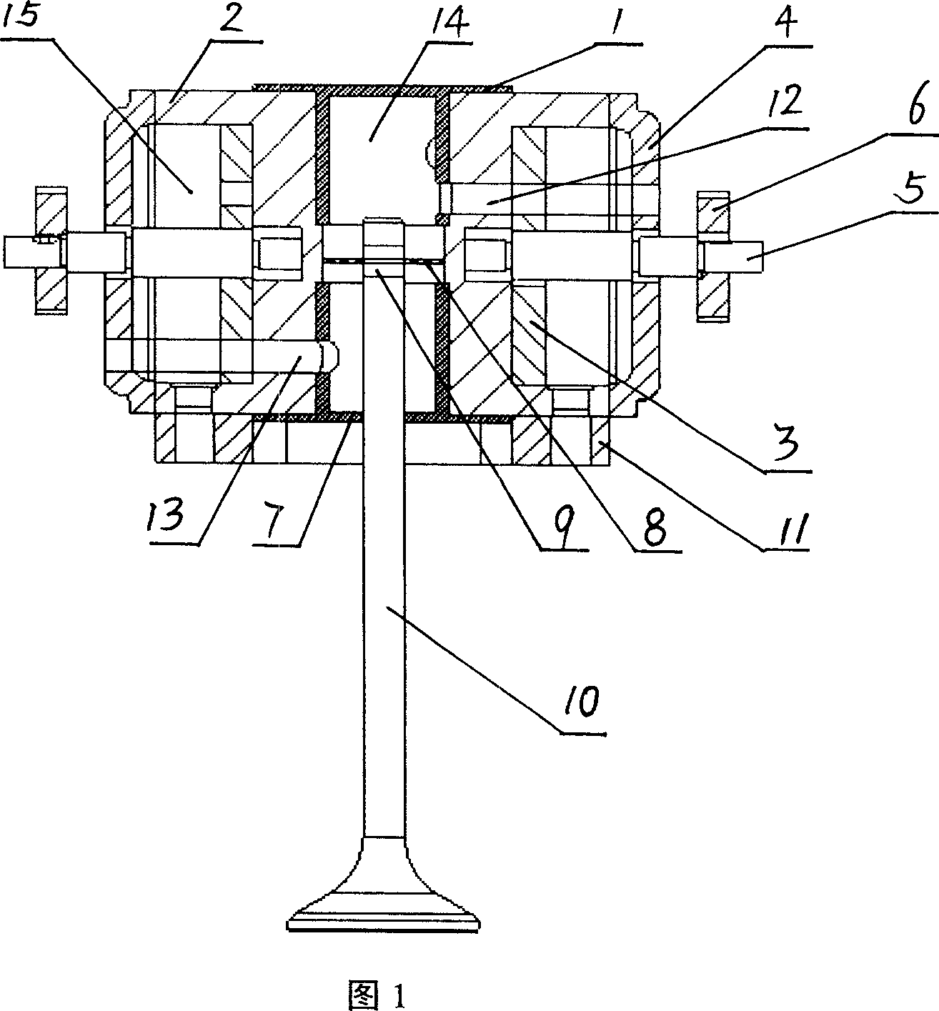
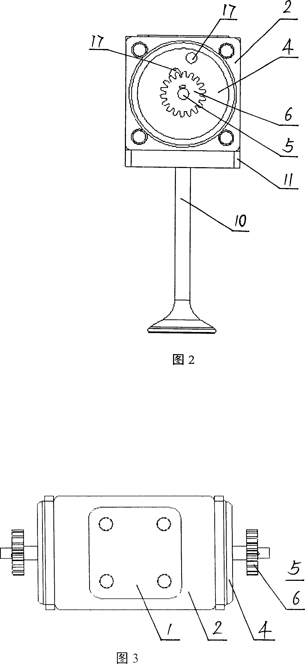
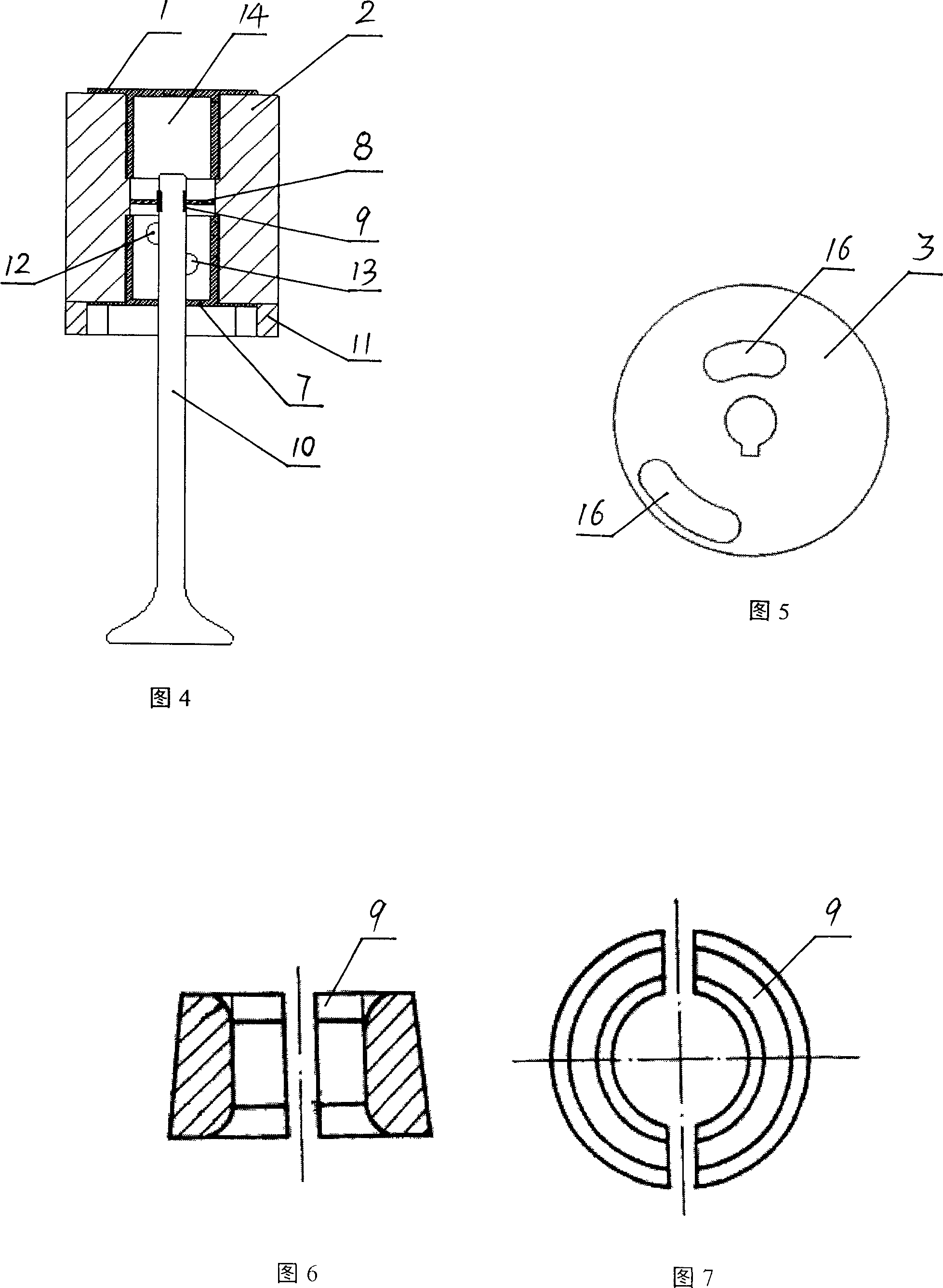
[0016] Referring to the accompanying drawings, the diesel engine hydraulically drives the valve distribution mechanism, including a hydraulic cylinder block 2, a valve 10, and a gear timing group. The hydraulic cylinder block 2 has a hydraulic chamber 14 that penetrates up and down and a timing disc chamber 15 that is symmetrically arranged on both sides of the hydraulic chamber 14 axially. Oil hole 13, oil return hole 12, the upper and lower ends of the hydraulic cylinder block 2 are sealed by the upper cylinder head 1 and the lower cylinder head 7, and the opposite inner ends of the upper cylinder head 1 and the lower cylinder head 7 have a hollow cavity communicating with the hydraulic chamber 14 , the cavity walls of the upper cylinder cover 1 and the lower cylinder cover 7 are provided with high-pressure oil inlet holes and oil return holes corresponding to the positions of the high-pressure oil inlet hole 13 and the oil return hole 12, and the upper cylinder cover 1 and t...


PUM


Abstract

The invention disclose a hydraulic driving valve distributor of diesel engine, comprising a hydraulic cylinder, a valve, a hydraulic chamber and a timing coil chamber on the hydraulic cylinder. The hydraulic cylinder is arranged with high-pressure oil inlet and reflux hole through to the timing disc chamber; the hydraulic cylinder via the upper and lower covers is sealed; the walls of the upper and lower covers are arranged with the high-pressure oil inlet and reflux hole; the timing coil chamber is mounted with a timing disc arranged with a rotary groove relative to the high-pressure oil inlet and reflux hole; the outer side of the timing coil chamber is mounted with a sealing cover; the sealing cover is arranged with holes passed through with the high-pressure oil inlet tube and the reflux tube; the timing disc is mounted with a correcting axle protruded outside the sealing cover; the outer end of the correcting axle is mounted a secondary gear meshed with the first gear on the first correcting axle; the hydraulic cylinder is arranged with a middle disc sliding upper and down; the rod of the valve through the lower cover and the clamper is connected to the middle disc.

Description

technical field [0001] The invention relates to a diesel engine hydraulic drive valve valve mechanism. Background technique [0002] At present, the valve mechanism of diesel engine mostly adopts the mechanical device that the cam directly or indirectly drives the valve. During operation, mechanical wear, clearance, and radial runout of the camshaft cause valve impact noise; the valve timing is affected by the shape and machining accuracy of the cam, making it difficult to correct intuitively. At the same time, the valve opens and seats slowly, As a result, the full valve opening time is short and the intake efficiency is low. Moreover, the processing of the cam-driven valve mechanism is complicated, and the technical requirements and costs are high. Contents of the invention [0003] The technical problem to be solved by the present invention is to provide a diesel engine with a gas distribution mechanism that can improve the efficiency of intake and exhaust, reduce noi...

Claims


Application Information

Patent Timeline
Patent Type & Authority Applications(China)
IPC IPC(8): F01L9/02F01L9/10
Inventor 朱杨
Owner WEICHAI POWER CO LTD
Learn More