Method and apparatus for detecting oscillations

A technology for diagnosing devices and detecting signals, applied in measurement devices, mufflers, exhaust devices, etc., can solve problems such as damage to system functions

Inactive Publication Date: 2011-03-30
ROBERT BOSCH GMBH
View PDF6 Cites 2 Cited by
  • Summary
  • Abstract
  • Description
  • Claims
  • Application Information

AI Technical Summary

Problems solved by technology

These oscillations may im...

Method used


Image

  • Method and apparatus for detecting oscillations
  • Method and apparatus for detecting oscillations
  • Method and apparatus for detecting oscillations

Examples


Embodiment Construction

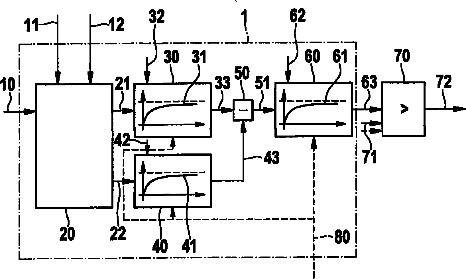
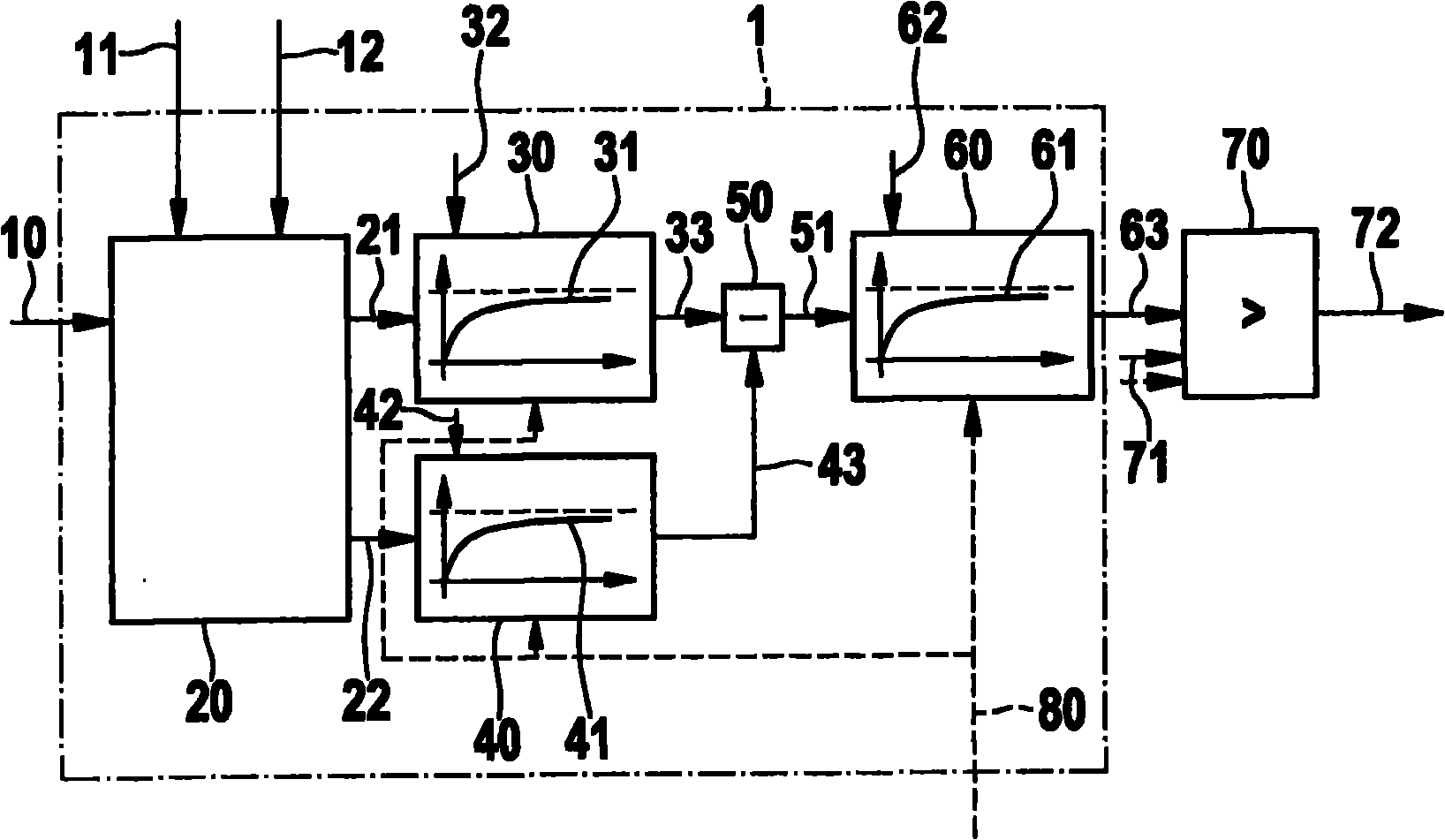
[0026] figure 1 A block diagram of a diagnostic device for detecting oscillations in a signal is shown. In this block diagram, a signal 10 to be evaluated is connected to the input of the diagnostic device 1 .

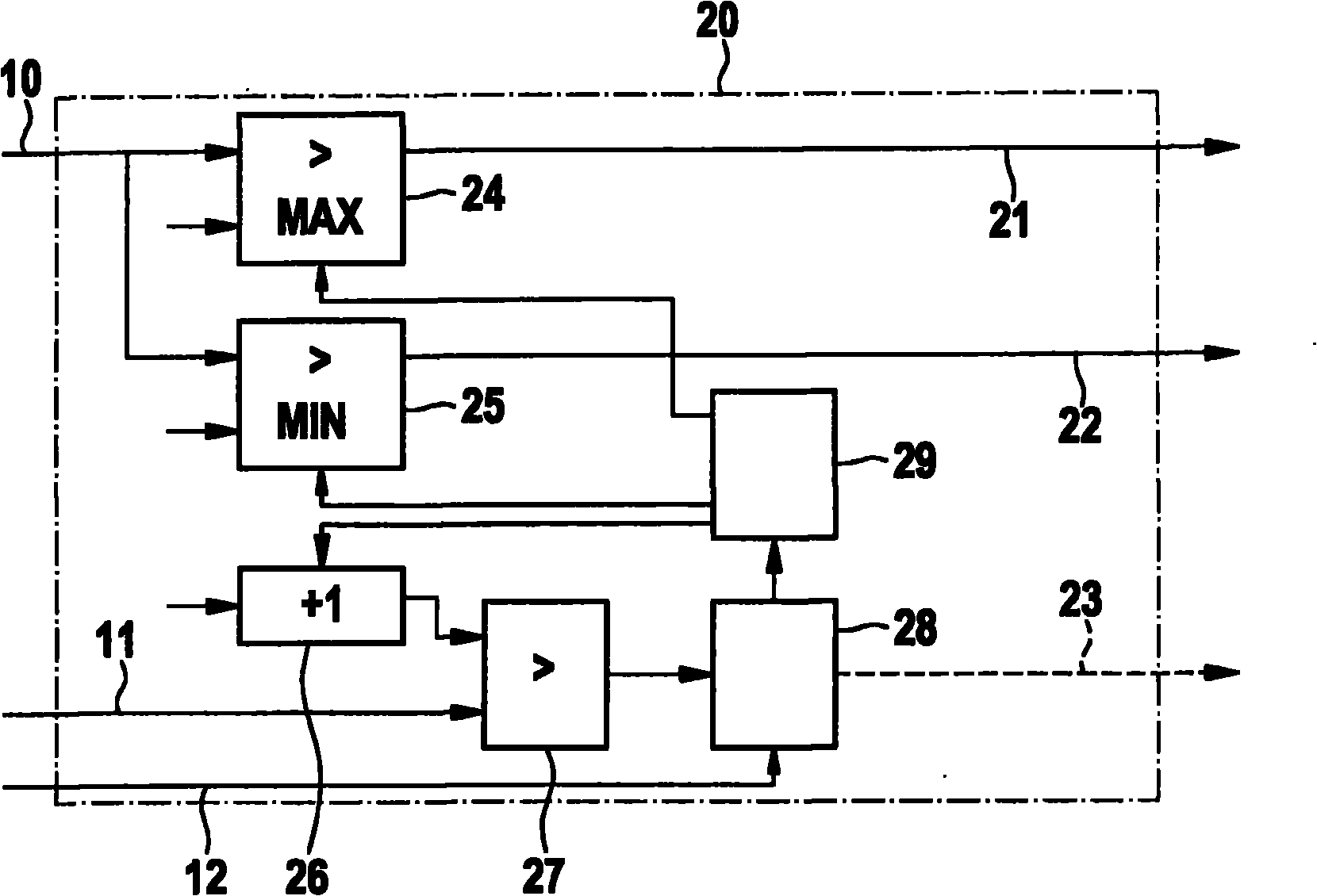
[0027] The diagnostic device 1 has a first processing unit 20 . With this processing unit it is possible to obtain from a certain definable number of values ​​n with signal 10 VALSelect the largest or smallest value 21, 22 in the signal segment of 11. The maximum or minimum values ​​21 , 22 can be filtered with a downstream low-pass filter unit 30 for filtering the maximum value 21 and a downstream low-pass filter unit 40 for filtering the minimum value 22 . The maximum and minimum values ​​33 , 43 thus filtered are passed as input parameters to the difference calculation unit 50 , wherein the amplitude value 51 can be processed as an output variable of the difference calculation unit 50 . In the example shown, this amplitude value is converted into a filtered ampl...


PUM


Abstract

The present invention relates to a method for detecting oscillations of signals, including evaluating signals to be analyzed concerning to occurrence of maximum or minimum values, by considering determined number of values in an evaluation section of the signals. The maximum or minimum values are filtered by low pass transfer functions with time constants, and the maximum or minimum values are reprocessed by differentiation of amplitude value, where the amplitude value is evaluated for analyzing oscillations of the signals. Furthermore, the invention also relates to a diagnosing device for detecting oscillations of signals, having a first evaluating unit to select maximum or minimum values from the signal section, the maximum or minimum values is filtered by a low pass filter unit respectively, and the filtered values are input to a difference calculating unit as input paremeters. The amplitude value can be processed as an output parameter of the difference calculating unit and is filtered by a following low pass filter unit, and/or the amplitude value is compared with a prescribed value by another processing unit.

Description

technical field [0001] The invention relates to a method for detecting oscillations in a signal. [0002] Furthermore, the invention relates to a corresponding diagnostic device for detecting oscillations in the signal. In the diagnostic device, the signal to be analyzed is connected to the input of the diagnostic device, and an output signal can be generated at the output, with which it can be shown that there are more than one or more Oscillations that determine the amplitude of a specified value. Background technique [0003] In technical systems vibrations or oscillations often occur in the signal. On the one hand, it can cause significant disturbances in signal measurement tasks or in signal processing, and on the other hand, it can lead to damage to the system if the amplitude of the oscillations increases over time and exceeds a critical value. To be able to detect these types of states one needs corresponding monitoring functions to protect system components from ...

Claims


Application Information

Patent Timeline
IPC IPC(8): G01D1/00F01N11/00F01N9/00F01N3/20
CPCY02T10/40F01N2550/05F02D2041/1432F02D41/22F02D41/28F01N3/208F01N2900/0404F01N2900/1808G01R19/04G01R19/2506G01R29/04Y02A50/20Y02T10/12
Inventor J·布劳恩
Owner ROBERT BOSCH GMBH
Why Eureka
Try Eureka