Method for optical switch and optical switch

An optical switch and grating technology, applied in the field of optical communication, can solve the problems of increasing the complexity of the structure, increasing the number of liquid crystal cells, etc.

Inactive Publication Date: 2011-03-30
HUAWEI TECH CO LTD
View PDF7 Cites 13 Cited by
  • Summary
  • Abstract
  • Description
  • Claims
  • Application Information

AI Technical Summary

Problems solved by technology

[0005] A liquid crystal unit is made into a 1X2 switch. If expansion and upgrading are required, if there are many switching channels, the number of liquid crystal units required will also increase accordingly, which will greatly increase the complexity of the structure

Method used


Image

  • Method for optical switch and optical switch
  • Method for optical switch and optical switch
  • Method for optical switch and optical switch

Examples


specific example

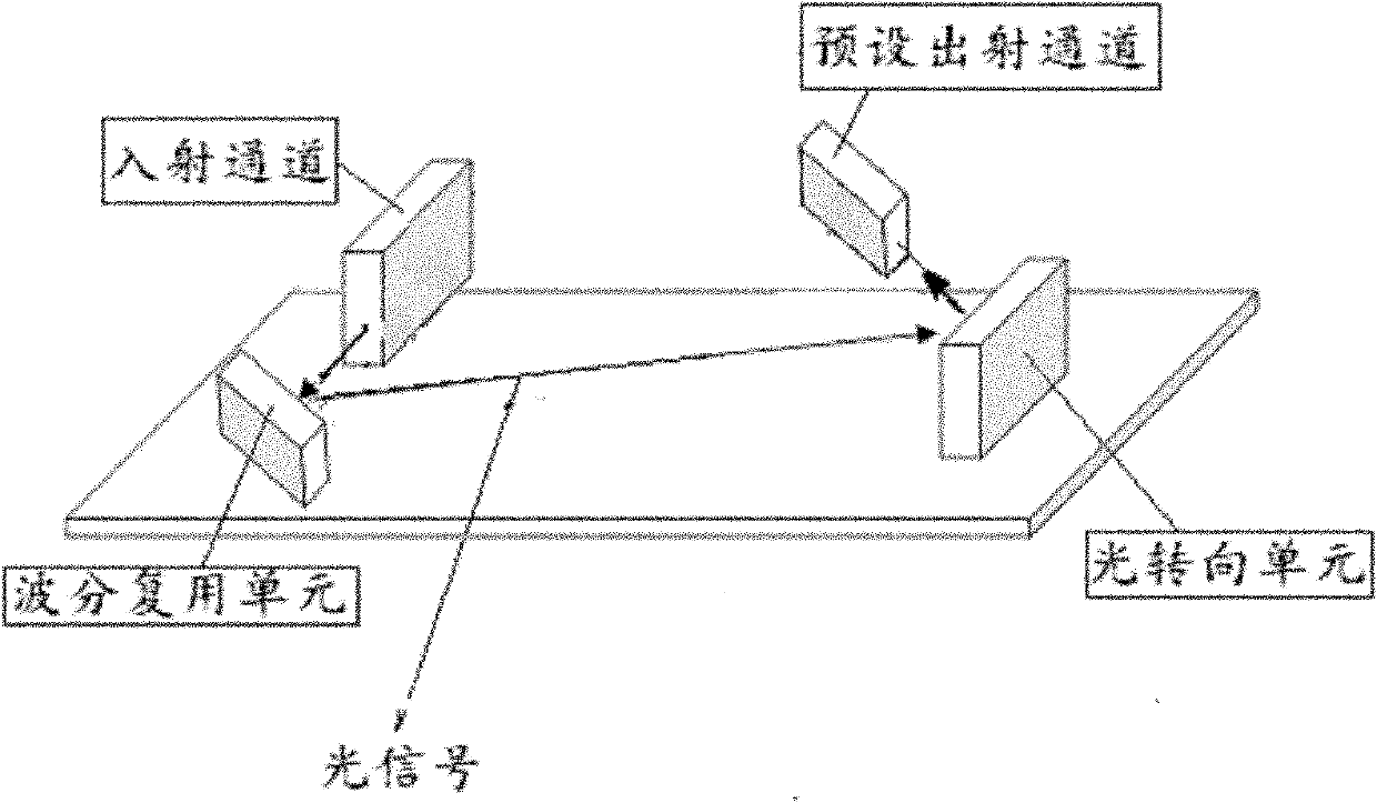
[0062] Optical signals with multiple wavelengths (for example: wavelengths λ1, λ2, λ3) are input from one incident channel, and optical signals with one wavelength (for example: wavelength λ4) are input from another incident channel. After passing through the optical steering unit, the wavelength The optical signal with wavelength λ1 and the optical signal with wavelength λ2 enter one preset outgoing channel, the optical signal with wavelength λ3 and the optical signal with wavelength λ4 enter another preset outgoing channel.

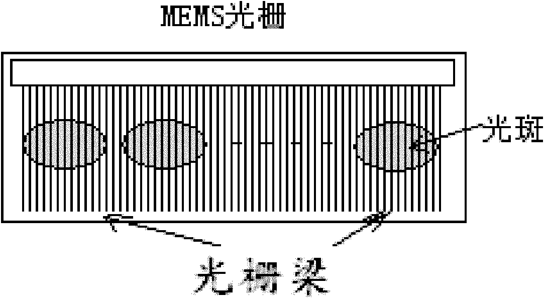
[0063] In an embodiment of the present invention, the plurality of MEMs grating beams may be a comb structure. The working width of the MEMs grating beam may be smaller than the diameter of the light spot. Among the plurality of MEMs grating beams, the working width of each MEMs grating beam may be different.

[0064] In the above-mentioned embodiment of the present invention, one light spot falls on a plurality of MEMs grating beams, and at least two ...


PUM


Abstract

The embodiment of the invention discloses a method for an optical switch and the optical switch. The optical switch comprises a light turning unit, wherein the light turning unit is used for turning a plurality of light beams and comprises a plurality of micro-electromechanical systems (MEMs) grating beams; the plurality of light beams fall on the plurality of MEMs grating beams to form a plurality of light spots; one light spot falls on at least two MEMs grating beams; one grating beam bears a part of one light spot; and at least two of the plurality of MEMs grating beams rotate in turn in batch, and at least one part of the one light spot is reflected to at least one preset exit channel.

Description

technical field [0001] The present invention relates to the technical field of optical communication, and more specifically, to an optical switch method and an optical switch. Background technique [0002] With the continuous increase of optical transmission capacity, the channel switching and networking complexity of optical communication is getting higher and higher. In order to meet the networking requirements, the intelligent wavelength switching in WDM (Wavelight Division Multiplexing, wavelength division multiplexing) transmission nodes The requirements are getting higher and higher, and optical switches with wavelength selection function have emerged as the times require. An existing optical switch for realizing wavelength selective crossover such as figure 1 shown. [0003] The optical switch utilizes the electro-optic characteristics of liquid crystals to change the phase characteristics and polarization characteristics of transmitted light, and adjust and control...

Claims


Application Information

Patent Timeline
Patent Type & Authority Applications(China)
IPC IPC(8): G02B26/08
CPCG02B26/0833H04J14/02G02B26/0808G02B5/1861G02B6/356G02B6/3518
Inventor 傅正华
Owner HUAWEI TECH CO LTD
Why Eureka
Try Eureka