
Ultra-high-density modular optical fiber distribution frame system

An optical fiber distribution frame, ultra-high-density technology, applied in the directions of light guides, optics, optical components, etc., can solve the inconvenient installation and maintenance of wiring optical cables or connecting optical cables, inconvenient equipment expansion, upgrade and maintenance, and functional module boxes that cannot be disassembled or assembled and other problems, to achieve the effect of easy expansion, upgrade and maintenance, low occupancy rate, and smooth pulling

Inactive Publication Date: 2020-01-10
长芯盛(武汉)科技股份有限公司
View PDF10 Cites 3 Cited by
  • Summary
  • Abstract
  • Description
  • Claims
  • Application Information

AI Technical Summary

Problems solved by technology

In the existing optical fiber distribution frame system, the connection between the distribution frame and the functional module box is usually a simple fixed connection method, and the functional module box cannot be flexibly disassembled from the distribution frame, which is not only inconvenient for wiring optical cables or connecting optical cables It also brings inconvenience to the expansion, upgrading and maintenance of later equipment. At the same time, this method is expensive and takes up a lot of space for wiring.
On the other hand, in the existing optical fiber distribution frame system, the fiber density per unit space (1U) is mostly 24, 48, 72, 96 cores (DLC), etc., usually the highest density does not exceed 96 cores (DLC), This can no longer meet the requirements of the development trend

Method used


Image

  • Ultra-high-density modular optical fiber distribution frame system
  • Ultra-high-density modular optical fiber distribution frame system
  • Ultra-high-density modular optical fiber distribution frame system

Examples


Embodiment Construction

[0047] In order to make the object, technical solution and advantages of the present invention clearer, the present invention will be further described in detail below in conjunction with the accompanying drawings and embodiments. It should be understood that the specific embodiments described here are only used to explain the present invention, not to limit the present invention.

[0048] In the description of the present invention, the terms "inner", "outer", "longitudinal", "transverse", "upper", "lower", "top", "bottom", "left", "right", "front" ", "rear" and other indicated orientations or positional relationships are based on the orientations or positional relationships shown in the drawings, and are only for the convenience of describing the present invention and do not require that the present invention must be constructed and operated in a specific orientation, so it should not be understood as Limitations on the Invention.

[0049] In addition, the technical feature...


PUM


Abstract

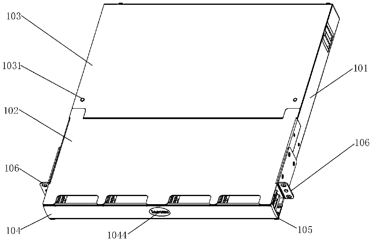
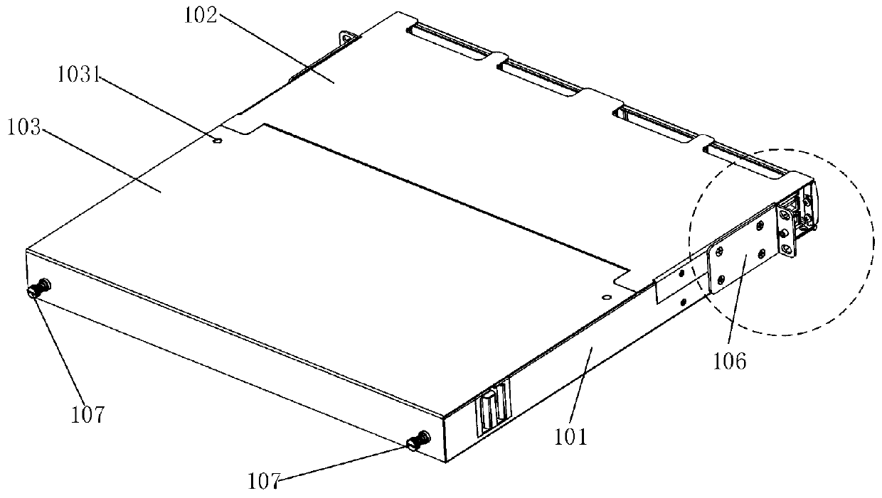
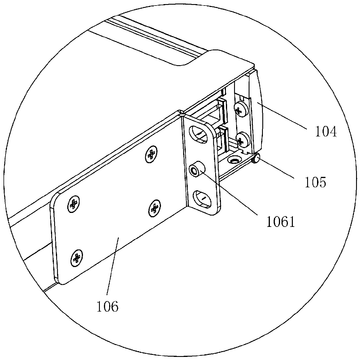
The invention relates to the technical field of optical fiber communication, and provides an ultra-high-density modular optical fiber distribution frame system comprising an optical fiber distributionframe and a functional module, wherein a box is formed in the optical fiber distribution frame, and a functional module is installed in the box; the optical fiber distribution frame comprises a plurality of chute modules and a plurality of pallets; the respective chute modules are fixed in the front area of the box, and a plurality of chutes superimposed at levels are arranged on the sides; eachof the pallets is fixed with a plurality of cable management handles to form module pallet assemblies, which slide into and out of the box through the cable management handles; side grooves are provided on the sides of the cable management handles, and the functional module is pushed into the module pallet assemblies along the side grooves; elastic limit edges are provided on the cable managementhandles, and support the functional module when pushing the functional module into the module pallet assemblies. In the ultra-high-density modular optical fiber distribution frame system provided by the invention, the respective module pallet assemblies can be moved into and out of the box body by sliding, and the functional module slides into the pallet, which is more convenient and flexible to disassemble. The ultra-high-density modular optical fiber distribution frame system is compact in structure and low in space occupation rate, and realizes ultra-high density.

Description

【Technical field】 [0001] The invention relates to the technical field of optical fiber communication, in particular to an ultra-high density modular optical fiber distribution frame system. 【Background technique】 [0002] In recent years, the continuous development of the information industry has made the demand for the integrated wiring industry more and more vigorous, and gradually replaced copper connections with optical fibers, and the pace of "light into copper and retreat" has accelerated. In today's information age, people's demand for information collection, processing, exchange, transmission, storage and security is increasing; realizing the scale development of data centers that provide these comprehensive service places for data can meet people's growing needs Information requirements also ensure the security of information and the disaster recovery capability in the event of emergencies. It not only takes into account the requirements of its own data for storage,...

Claims


Application Information

Patent Timeline
IPC IPC(8): G02B6/44
CPCG02B6/4452
Inventor 孔光黄维祝辉黄亚元曹利华熊爽李明猛邓涛
Owner 长芯盛(武汉)科技股份有限公司
Learn More