Display device, correction system, forming device, determining device and method
A display device and technology for display, applied in static indicators, instruments, etc., can solve the problems of uneven strip shape and uneven characteristics of polysilicon
- Summary
- Abstract
- Description
- Claims
- Application Information
AI Technical Summary
Problems solved by technology
Method used
Image
Examples
Embodiment approach 1
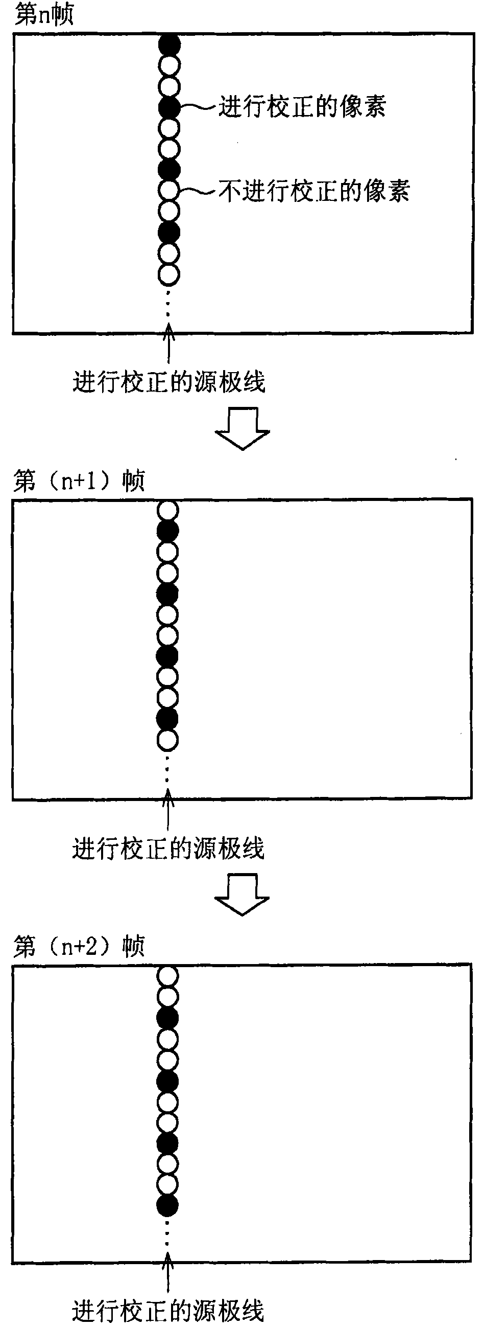
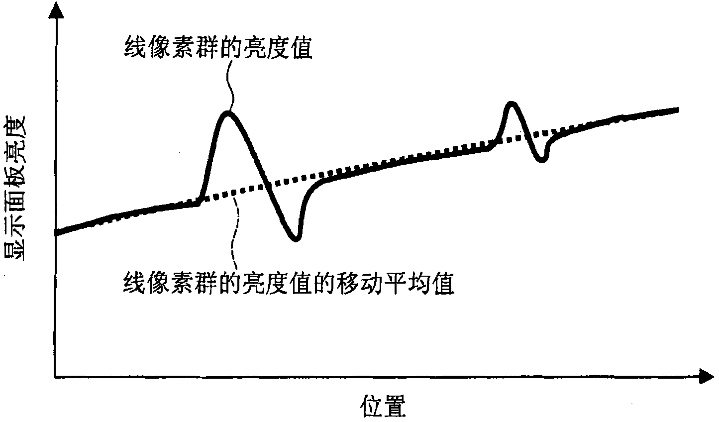
[0122] One embodiment of the present invention will be described below. In this embodiment, the correction of the stripe-shaped unevenness (striped brightness unevenness) that appears on the display device parallel to the extending direction of the source lines (data lines, data signal lines) is taken as an example. Note that this display device is, for example, a transmissive liquid crystal display device that displays based on image data expressing RGB colors with 6 bits, which is included in a mobile device such as a cellular phone. However, the applicable objects of the present invention are not limited thereto.
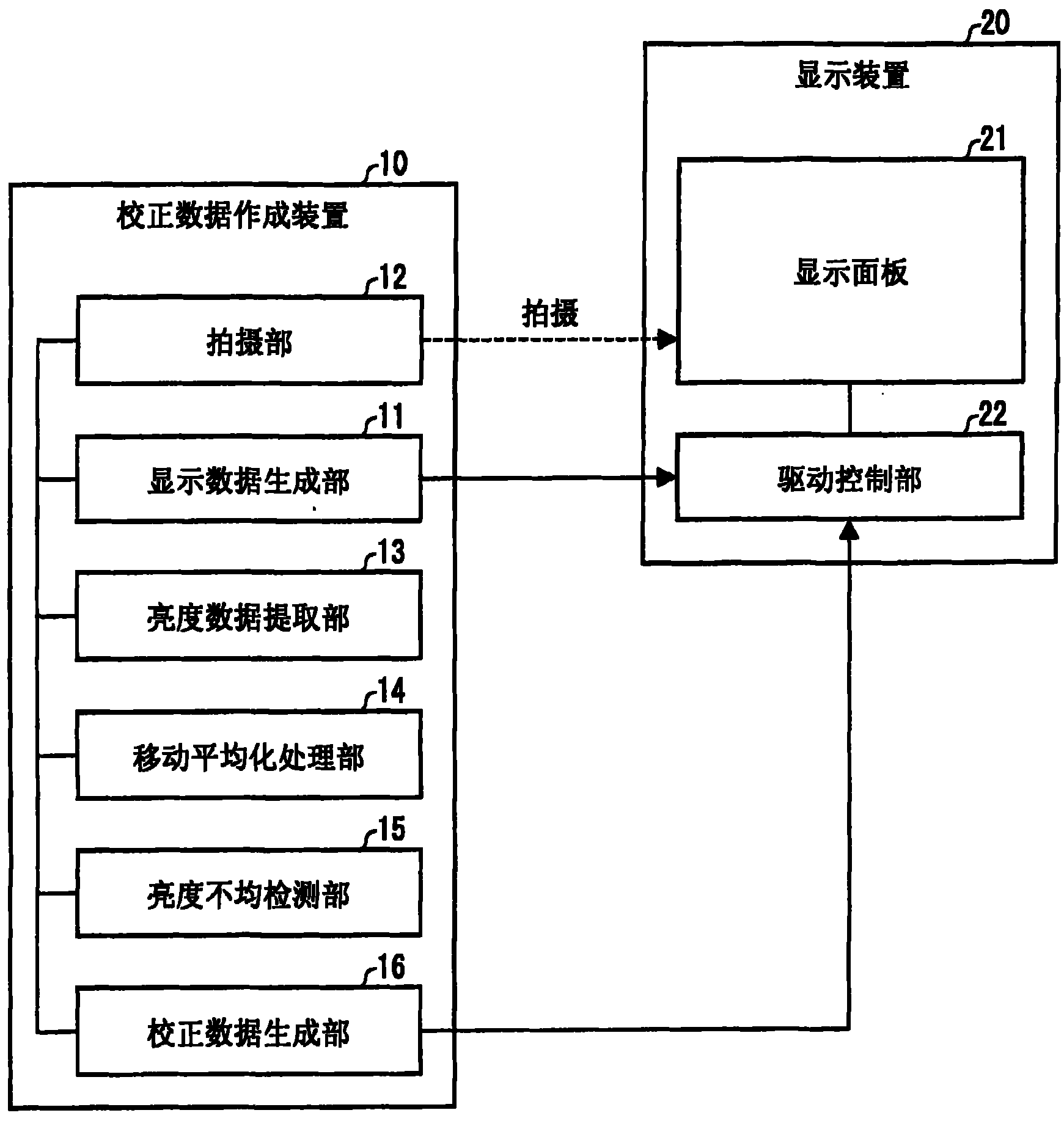
[0123] figure 2 It is a block diagram showing the configuration of the correction data creating device 10 of this embodiment. As shown in the figure, correction data generation device 10 includes display data generation unit 11 , imaging unit 12 , brightness data extraction unit 13 , moving average processing unit 14 , brightness unevenness detection unit 15 ,...
Embodiment approach 2
[0197] Next, other embodiments of the present invention will be described. For the sake of convenience, components having the same functions as those described in Embodiment 1 are given the same reference numerals, and description thereof will be omitted.
[0198] In Embodiment 1, the configuration for correcting streak unevenness was described. In this embodiment, an example of a configuration for correcting localized unevenness (spotty unevenness) will be described.
[0199] Figure 11 It is a block diagram showing the configuration of the correction data creating device 10b of this embodiment. As shown in the figure, instead of the moving average processing unit 14, brightness unevenness detecting unit 15, and corrected data generating unit 16 of the correction data creating device in Embodiment 1, the corrected data creating device 10b includes a moving averaging processing unit 14b, The brightness unevenness detection part 15b and the correction data generation part 16...
Embodiment approach 3
[0239] Next, other embodiments of the present invention will be described. For the sake of convenience, components having the same functions as those described in the above-mentioned embodiments are given the same reference numerals, and descriptions thereof are omitted.
[0240] In this embodiment, the explanation will be given mainly on the connection between the source lines ( Examples of correcting stripe-like uneven brightness (striped uneven brightness) and localized spot-like uneven brightness (spot-like uneven brightness) in which the extending directions of data lines and data signal lines are parallel. That is, in the present embodiment, it is described that a plurality of parallel gate lines (scanning signal lines) and a plurality of parallel source lines intersect each other and each of the gate lines and the source lines intersect each other. An example of correcting the striped uneven brightness parallel to the source lines and the local spot uneven brightness i...
PUM
 Abstract
Description
Claims
Application Information
 - R&D
- Intellectual Property
- Life Sciences
- Materials
- Tech Scout
- Unparalleled Data Quality
- Higher Quality Content
- 60% Fewer Hallucinations
Browse by: Latest US Patents, China's latest patents, Technical Efficacy Thesaurus, Application Domain, Technology Topic, Popular Technical Reports.
© 2025 PatSnap. All rights reserved.Legal|Privacy policy|Modern Slavery Act Transparency Statement|Sitemap|About US| Contact US: help@patsnap.com


