Eureka AIR delivers breakthrough ideas for toughest innovation challenges, trusted by R&D personnel around the world.

Device and method for reducing standby power consumption of display device and display device with low standby power consumption

Inactive Publication Date: 2011-03-30
上海立隆微电子有限公司
View PDF5 Cites 6 Cited by
  • Summary
  • Abstract
  • Description
  • Claims
  • Application Information

AI Technical Summary

Problems solved by technology

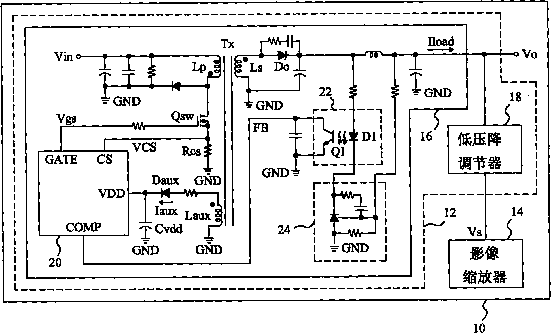
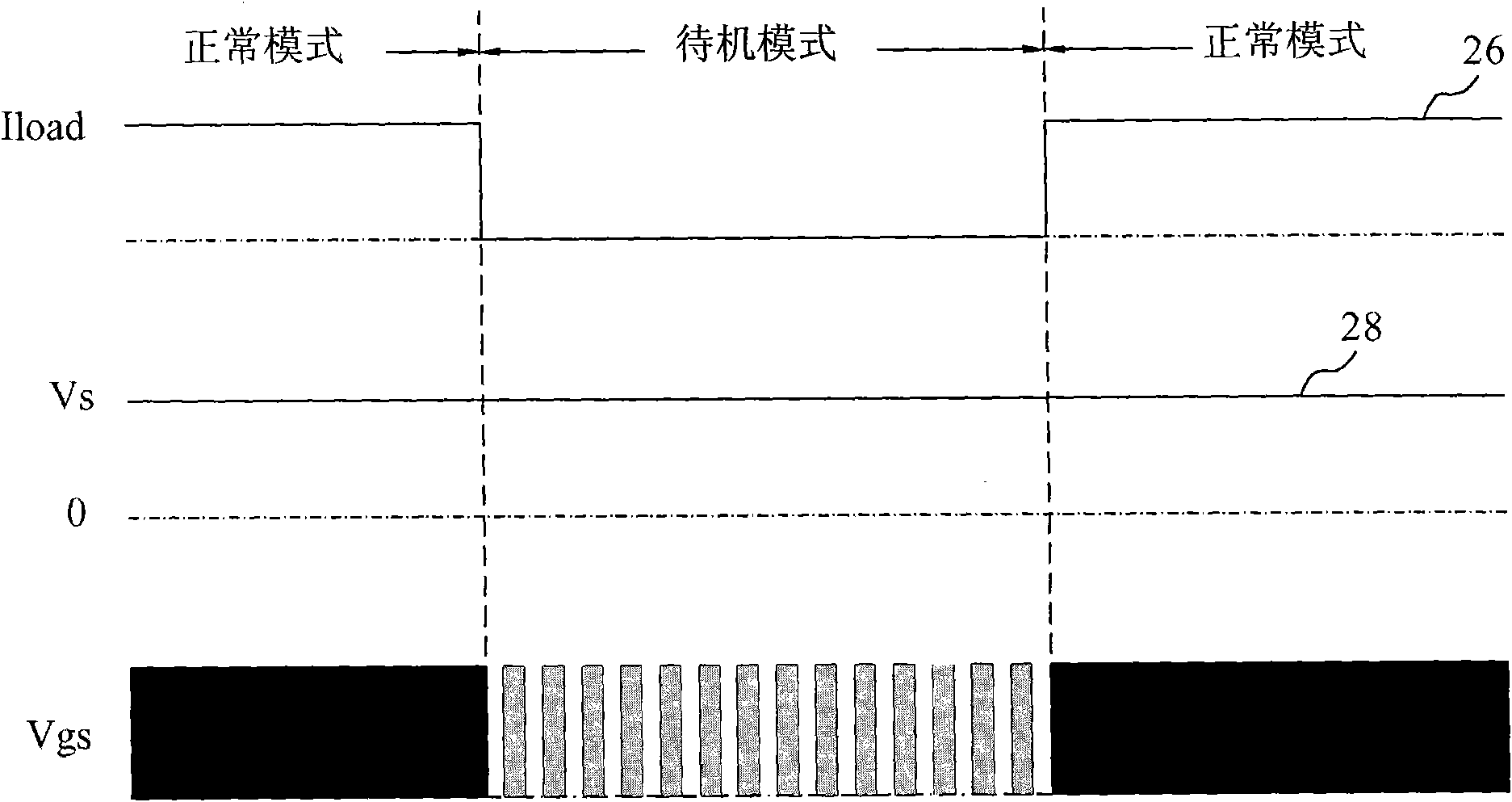
However, the known technology does not effectively adjust the power consumption of the image scaler 14 in the standby mode. As shown in the waveform 28, the power supply voltage Vs of the image scaler 14 is maintained at a fixed value regardless of the normal mode or the standby mode.
After the display 10 enters the standby mode, because the image scaler 14 and the power controller 20 still maintain normal operation, the power consumption is still very large; if the image scaler 14 is turned off for power saving, the display 10 also enters the shutdown mode, In this way, the meaning of standby is lost.
[0004] Therefore, there are above-mentioned inconveniences and problems in the known devices and control methods thereof for reducing display power consumption during standby.

Method used


Image

  • Device and method for reducing standby power consumption of display device and display device with low standby power consumption
  • Device and method for reducing standby power consumption of display device and display device with low standby power consumption
  • Device and method for reducing standby power consumption of display device and display device with low standby power consumption

Examples


Embodiment Construction

[0057] The present invention will be further described below in conjunction with embodiment and accompanying drawing.

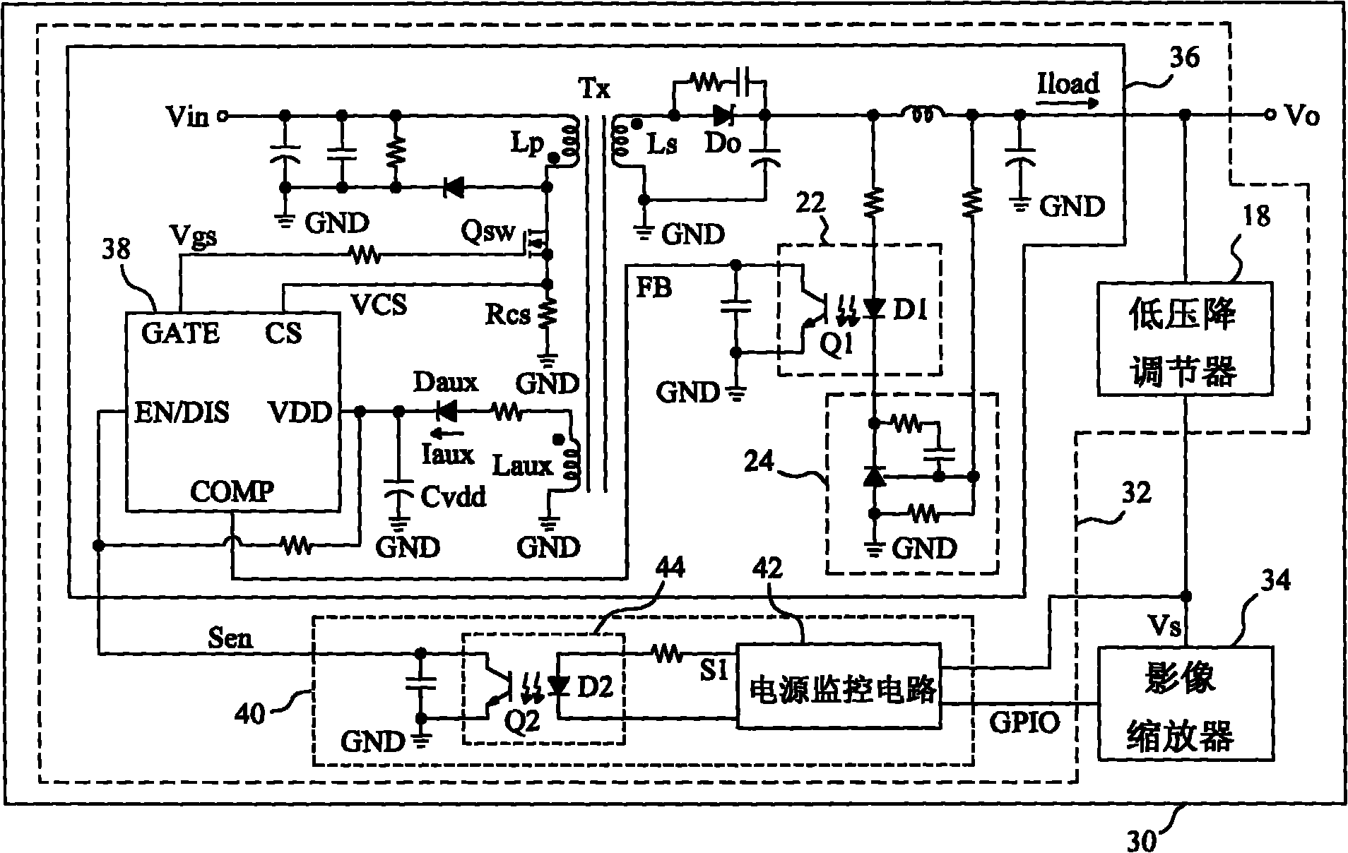
[0058] see now image 3 , image 3 is a schematic diagram of an embodiment of the present invention. As shown, the display 30 includes a power supply system 32 to supply voltages required by its internal components, and an image scaler 34 to control the size of the displayed image. The power supply system 32 includes a flyback voltage converter 36, which uses a power controller 38 to switch a power switch Qsw, converts an input voltage Vin to an output voltage Vo, and a low-dropout regulator 18 generates a voltage Vs from the voltage Vo to supply the video scaler 34. The power supply system 32 further includes a device 40 for improving the standby efficiency of the display 30 , which includes a power monitoring circuit 42 connected to the image scaler 34 , and an optocoupler 44 connected to the power controller 38 . The power monitoring circuit 42 receive...


PUM


Abstract

The invention relates to a device for reducing standby power consumption of a display device, the display device comprises a power supply system which is used for controlling power transmission through a power changeover switch of a power supply controller, and an image zooming device which is used for receiving power supply voltage from the power supply system, and the device is characterized in that the device comprises a power supply monitoring circuit and an optical coupler, wherein the power supply monitoring device is used for monitoring the power supply voltage under the control of a mode signal during the standby mode, and accordingly producing a control signal; the optical coupler is connected with the power supply monitoring circuit and used for converting the control signal to an enable signal, and sending the enable signal to the power supply controller so as to enable or close the power supply controller. The device and the method for reducing the standby power consumption of the display device have the advantages of reducing changeover loss, reducing the power consumption and maintaining that the power supply voltage is sufficient to lead the image zooming device to operate normally.

Description

technical field [0001] The invention relates to a power management of a display, in particular to a device and method for reducing the power consumption of the display when it is in standby. Background technique [0002] In recent years, in response to energy shortages and increased awareness of environmental protection, more and more attention has been paid to the energy-saving and power-saving functions of power supplies. Among them, the power consumption during standby is also a very important part. Such as figure 1 As shown, the display 10 uses a power supply system 12 to supply voltages required by its internal components, and a video scaler (scalar) 14 is used to control the size of the displayed video. The power supply system 12 converts the input voltage Vin to an output voltage Vo using a flyback voltage converter 16 , and the voltage Vs used by the image scaler 14 is generated from the voltage Vo using a low-dropout regulator 18 . In the voltage converter 16, the...

Claims


Application Information

Patent Timeline
Patent Type & Authority Applications(China)
IPC IPC(8): G09G5/00G09G5/373
Inventor 张光甫陈佑民黄培伦
Owner 上海立隆微电子有限公司
Why Eureka
Eureka Blog
Learn More