
Container

A container and shell technology, which is applied in the field of containers for storing solid-state source materials, can solve the problems affecting the cleanliness of the evaporation device and easy leakage to the outside of the chamber, and achieve the effect of ensuring personal safety and convenient use

Inactive Publication Date: 2013-02-27
SEMICON MFG INT (SHANGHAI) CORP
View PDF1 Cites 0 Cited by
  • Summary
  • Abstract
  • Description
  • Claims
  • Application Information

AI Technical Summary

Problems solved by technology

[0009] The purpose of the present invention is to provide an easy-to-use container to solve the problem that during the use of the existing container, the solid source material is easily leaked to the outside of the chamber and affect the cleanliness of the evaporation device, and to ensure that the operator personal safety

Method used


Image

  • Container
  • Container
  • Container

Examples


Embodiment Construction

[0029] The container proposed by the present invention will be described in further detail below in conjunction with the accompanying drawings and specific embodiments. Advantages and features of the present invention will be apparent from the following description and claims. It should be noted that the drawings are all in a very simplified form and use imprecise ratios, which are only used to facilitate and clearly assist the purpose of illustrating the embodiments of the present invention.

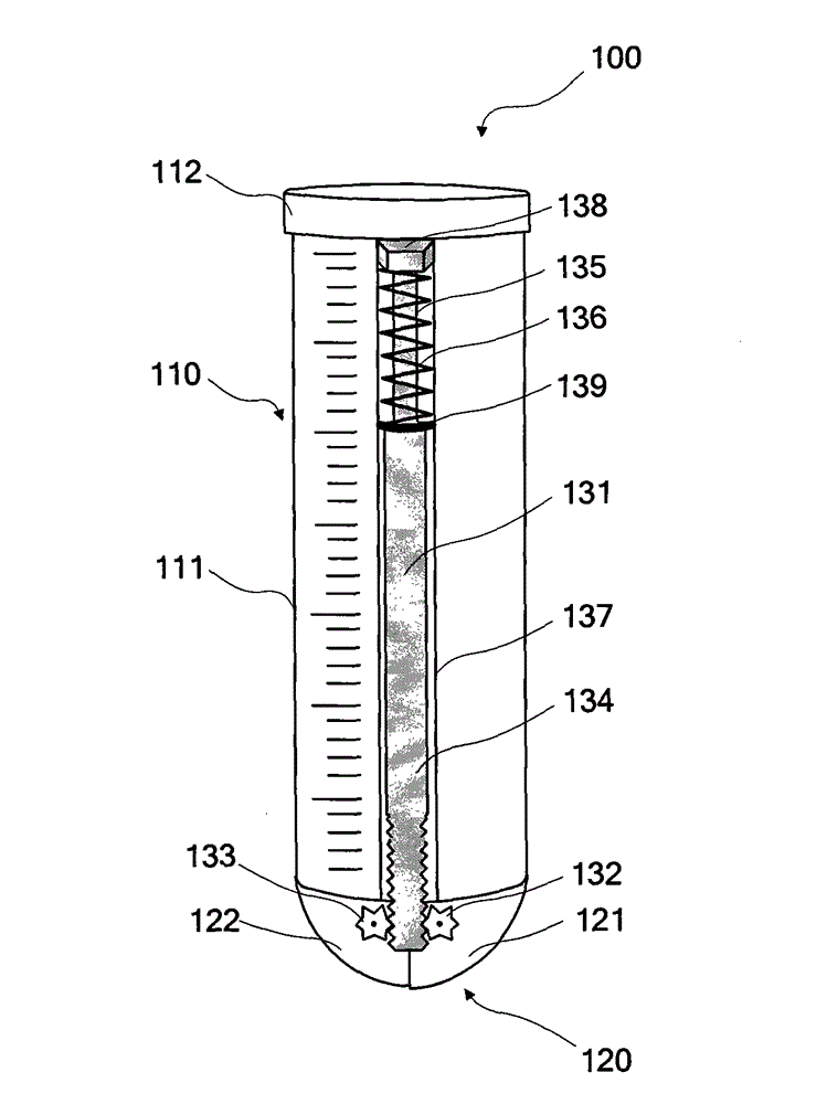
[0030] For details, please refer to Figure 3 to Figure 5 , and combined with figure 1 ,in, image 3 It is a schematic structural diagram of a container provided by an embodiment of the present invention, Figure 4 for image 3 A schematic diagram of the middle cover in an open state, Figure 5 for image 3 The plan view of the middle top cover and the mesh cover. As shown in the figure, the container 100 provided by an embodiment of the present invention includes: a main body 11...


PUM


Abstract

The invention discloses a container. The container comprises a main body, a cover body and a driving device, wherein the main body comprises a shell and a chamber for storing a substance; the cover body comprises a first cover and a second cover which are connected with the shell through shaft pins and jointed on the inner surface of the shell; the driving device is arranged outside the shell and connected with the first cover and the second cover; when the cover body is in a closed state, the edge of the first cover is partially overlapped with the edge of the second cover; and when the cover body needs opening, the first cover and the second cover are driven by the driving device to rotate so that the first cover and the second cover are relatively staggered to form a gap, and the substance can flow out of the gap. The container is convenient to use, and can prevent the source material from leaking to the exterior of the chamber to affect the cleanliness of an evaporation device, ensure the personnel safety of an operator, accurately control the quantity of the source material filled into a crucible and prevent deliquescence of the source material.

Description

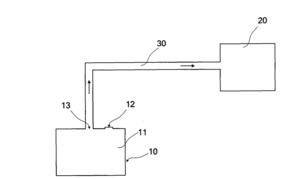
technical field [0001] The invention relates to the field of integrated circuit manufacturing, in particular to a container for storing solid source materials. Background technique [0002] Ion implantation is a very important technology in the field of integrated circuits. It uses ion implantation equipment to achieve semiconductor doping, that is, an ion beam with a certain charge and energy is injected into the wafer after being accelerated by an electric field and selected by a magnetic field. Change or adjust the electrical properties of certain parts of the wafer. [0003] Existing ion implantation equipment usually includes an ion source device, which is used to ionize the elements to be doped. For details, please refer to figure 1 , which is a schematic diagram of an existing ion source device. As shown in the figure, the ion source device includes an evaporation device 10 and an ionization chamber 20, and the evaporation device 10 includes a heat-conducting crucibl...

Claims


Application Information

Patent Timeline
Patent Type & Authority Patents(China)
IPC IPC(8): H01L21/48
Inventor 许鹖
Owner SEMICON MFG INT (SHANGHAI) CORP
Learn More