Method for realizing Ethernet path protection switching

A path protection and protection switching technology, applied in the field of network communication, can solve problems such as non-existent solutions, achieve the effects of reducing nodes, enhancing robustness, and ensuring reliability

Inactive Publication Date: 2011-03-30
ZTE CORP
View PDF4 Cites 11 Cited by
  • Summary
  • Abstract
  • Description
  • Claims
  • Application Information

AI Technical Summary

Problems solved by technology

However, no such solu

Method used


Image

  • Method for realizing Ethernet path protection switching
  • Method for realizing Ethernet path protection switching
  • Method for realizing Ethernet path protection switching

Examples


example 1

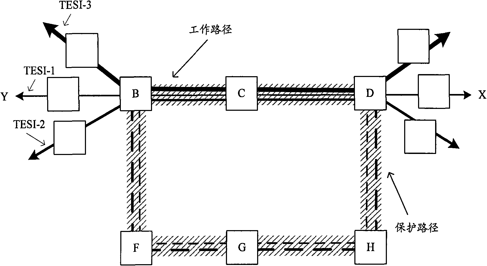
[0075] like Figure 4As shown, B-C-D is the bearer path of the end-to-end TESI, namely TESI-1 and TESI-2, B-C-D is the working path, and B-F-G-H-D is the protection path of the working path. Working paths and protection paths form a path protection group. Configure the protection objects of the trail protection group as TESI-1 and TESI-2 on endpoints B and D of the protection group respectively. It is assumed that the B-VID of Y→X of TESI-1 to ESP is 1, and the B-VID of reverse ESP is 2; the B-VID of N→M of TESI-2 to ESP is 3, and the B-VID of reverse ESP is 3. VID is 4. Figure 4 middle, Indicates the trail protection group; TESI-1 and TESI-2 are respectively represented by different thick solid lines, TESI-2 is the thickest, and TESI-1 is the thinnest. bridge device with express. In the table corresponding to each node, dark fonts indicate that the outgoing ports corresponding to the ESP are divided into working outgoing ports and backup outgoing ports; light fonts i...

example 2

[0078] like Figure 5 As shown, B-D is the bearer path of the end-to-end TESI, namely TESI-1 and TESI-2, B-D is the working path, and B-C-D and B-E-D are both protection paths of the working path. A working path and two protection paths form a path protection group. Configure the protection objects of the trail protection group as TESI-1 and TESI-2 on endpoints B and D respectively. It is assumed that the B-VID of Y→X of TESI-1 to ESP is 1, and the B-VID of reverse ESP is 2; the B-VID of N→M of TESI-2 to ESP is 3, and the B-VID of reverse ESP is 3. VID is 4. Figure 5 middle, represents the protection group; TESI-1 and TESI-2 are respectively represented by different thick solid lines, TESI-2 is the thickest and TESI-1 is the thinnest. bridge device with express. In the table corresponding to each node, dark fonts indicate that the outgoing ports corresponding to the ESP are divided into working outgoing ports and backup outgoing ports; light fonts indicate that there ...


PUM


Abstract

The invention discloses a method for realizing Ethernet path protection switching, which comprises the following steps of: setting a TESI (Traffic Engineering Service Instance) protected by a protection group; carrying out state detection on a working entity and a protection entity; and realizing path protection switching according to an output port configured for an ESP (Ethernet Switching Path) of the TESI on the endpoint of the protection group, as well as a corresponding protection switch mechanism selected in the current state detection. The invention also discloses a system for realizing Ethernet path protection switching, and a switching unit in the system is used for realizing path protection switching according to the output port configured for the ESP (Ethernet Switching Path) of the TESI on the endpoint of the protection group, as well as the corresponding protection switch mechanism selected in the current state detection. The method and the system disclosed in the invention can be used for improving failure recovery speed, reducing nodes for protection switching, facilitating network optimization and ensuring the reliability of end-to-end traffic flow.

Description

technical field [0001] The invention relates to the technical field of network communication, in particular to a method and system for switching Ethernet path protection in data communication. Background technique [0002] With the introduction of the concept of Carrier Ethernet (CE, Carrier Ethernet) to meet the needs of telecom networks, a connection-oriented Ethernet technology - Provider Backbone Transport (PBT, Provider Backbone Transport) also surfaced in October 2005. Since then, operators at home and abroad have adopted PBT technology to form a network, which provides a good start for the development of PBT technology in the metropolitan area network. [0003] The basis of PBT technology is the Provider Backbone Bridge (PBB, Provider Backbone Bridge) technology defined by the IEEE 802.1ah standard. IEEE calls PBT technology the Provider Backbone Bridge Traffic Engineering that supports traffic engineering (PBB-TE, Provider Backbone Bridge Traffic Engineering). . Th...

Claims


Application Information

Patent Timeline
IPC IPC(8): H04L12/24H04L1/22H04L45/24H04L45/28
CPCH04L12/413H04L43/0817H04L41/0681H04L41/0654H04L45/22H04L45/28
Inventor 魏月华
Owner ZTE CORP
Why Eureka
Try Eureka