
Intelligent infrared thermography imaging system

An infrared heat map and imaging system technology, applied in the field of medical equipment, can solve problems such as environmental interference and achieve high-precision results

Active Publication Date: 2011-04-06
TSINGHUA UNIV
View PDF3 Cites 12 Cited by
  • Summary
  • Abstract
  • Description
  • Claims
  • Application Information

AI Technical Summary

Problems solved by technology

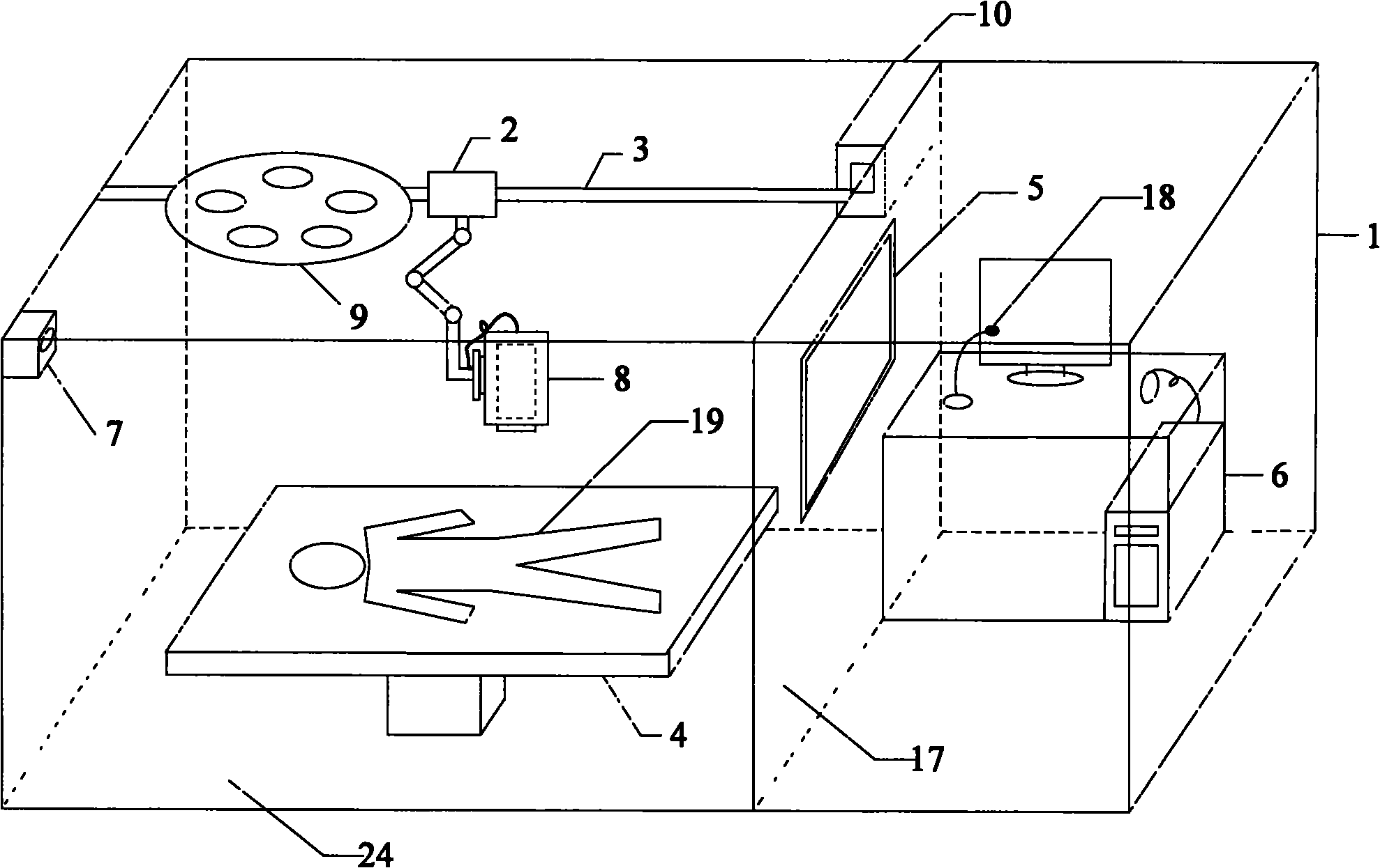
[0004] In order to overcome the deficiencies in the above-mentioned prior art, the object of the present invention is to provide an intelligent infrared thermal image imaging system, which manipulates infrared thermal image imaging by using the positioning module and focusing module inside the microcomputer of the infrared thermal image imaging control room The camera position positioning system is used to locate and focus the corresponding infrared thermal image imaging camera, so as to complete the infrared imaging operation of the patient on the hospital bed below it, realizing intelligent operation, eliminating the need for manual operation to adjust the focus and the detection personnel on the spot The operation will inevitably walk around in the detection room and cause interference to the environment, so that the infrared heat map with high accuracy and uniform standard environment can be obtained, providing a more objective and scientific reference for the diagnosis of clinical radiologists

Method used


Image

  • Intelligent infrared thermography imaging system
  • Intelligent infrared thermography imaging system
  • Intelligent infrared thermography imaging system

Examples


Embodiment Construction

[0016] The present invention will be described in more detail below in conjunction with the accompanying drawings.

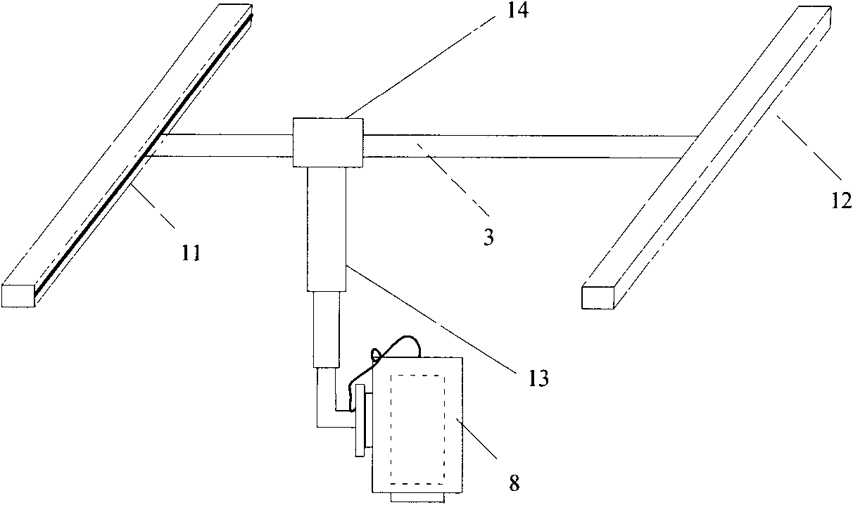
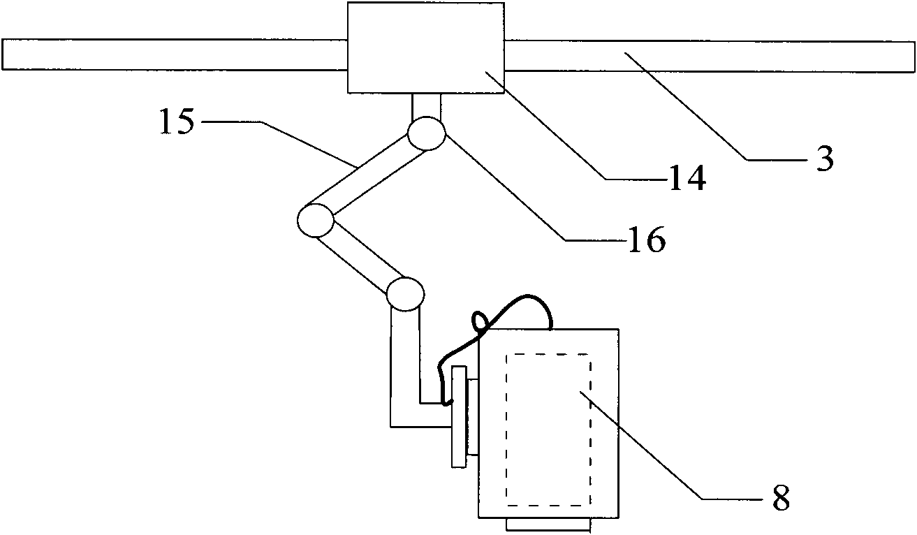
[0017] Such as figure 1 As shown, the intelligent infrared heat map imaging system includes an infrared heat map imaging camera 8, and also includes a microcomputer 6 including a positioning module 22 and a focusing module 23 arranged in the infrared heat map imaging control room 1, and the infrared heat map imaging The control room 1 uses a partition 17 with an observation window 5 to separate the horizontal guide rail device 3 arranged above the sick bed 4 in the adjacent infrared thermal image imaging room 24, and the infrared thermal image imaging camera position positioning system 2 is arranged on the guide rail device 3. The infrared heat map imaging camera position positioning system 2 is connected with the infrared heat map imaging camera 8, and the positioning control port 25 and the focusing control port 26 of the microcomputer 6 are connected with the...


PUM


Abstract

The invention relates to an intelligent infrared thermography imaging system. In the invention, a locating module and a focusing module in a microcomputer of an infrared thermography imaging control chamber are utilized to operate an infrared thermography imaging camera position locating system to locate and focus a corresponding infrared thermography imaging camera, thereby finishing infrared imaging operation on a patient in a sickbed below the infrared thermography imaging camera, realizing intelligent operation and avoiding the disadvantage of interference on environment caused by focal length through manual operation and inevitable walk of detecting personnel in a detection chamber during field operation, therefore, the invention can obtain higher accuracy and an infrared thermography in a unified standard environment and provides more objective scientific reference to diagnosis of a doctor of clinical picture department.

Description

technical field [0001] The invention relates to a medical device, in particular to an intelligent infrared thermal image imaging system. Background technique [0002] At present, with the continuous mining of various physiological and pathological information interpreted by medical infrared thermal images, the scope of application of this method is constantly expanding, especially in the detection, diagnosis and prognosis analysis of nerve, muscle and bone injuries. Unique value, so infrared thermographic imaging has been favored by clinicians for its advantages of non-contact and no side effects. [0003] However, due to the non-intelligence of the current infrared thermal imaging system, it has always been the main difficulty faced by radiologists. The non-intelligence leads to manual operation of the imaging process, which often causes inaccurate focus and insufficient image resolution, and the detection personnel cannot operate on the spot. Avoid walking in the detectio...

Claims


Application Information

Patent Timeline
IPC IPC(8): A61B5/00
Inventor 金超刘静杨阳
Owner TSINGHUA UNIV
Learn More