Laser welding fixture for power batteries

A technology for laser welding fixtures and battery fixtures, applied in laser welding equipment, welding equipment, welding equipment and other directions, can solve the problems of inability to guarantee the quality of power battery laser welding and low reliability of laser welding, and achieve significant production practical significance and improvement. High quality pass rate and high welding efficiency

Active Publication Date: 2011-04-06
TIANJIN LISHEN BATTERY
6 Cites 14 Cited by

AI-Extracted Technical Summary

Problems solved by technology

However, the reliability of laser welding is not high now, and it is impos...

Method used

In addition, adopt the seesaw structure that seesaw seat 18 and seesaw 17 are formed, can guarantee that when welding, power battery is completely buried in the U-shaped groove of battery fixture positioning plate 7, and power battery 2 is carried out During feeding, the power battery 2 can be jacked up by squeezing the seesaw 17, so that the power battery 2 is higher than the top surface of the battery fixture positioning plate 7, which is convenient for the operat...

Abstract

The invention discloses a laser welding fixture for power batteries. The fixture comprises a bottom plate (1), wherein two limiting plates (15) used for welding are arranged at the rear end of the bottom plate (1) at an interval; a sliding table cylinder (9) is respectively arranged right ahead each limiting plate (15) used for welding; a battery fixture positioning plate (7) and a mobile limiting plate (14) are respectively arranged on the upper surface of each sliding table cylinder (9) in tandem; at least one battery fixture guide shaft (12) is respectively fixed to the left end and the right end of each battery fixture positioning plate (7); each mobile limiting plate (14) is connected with each battery fixture positioning plate (7) through the battery fixture guide shaft (12); and a groove is reserved in the middle of each battery fixture positioning plate (7). The laser welding fixture for the power batteries disclosed by the invention can maintain the stability of battery clamping, ensures the welding reliability of the power batteries in various welding fields, and improves the quality passing rate of the power batteries.

Application Domain

Technology Topic

Image

  • Laser welding fixture for power batteries
  • Laser welding fixture for power batteries
  • Laser welding fixture for power batteries

Examples

  • Experimental program(1)

Example Embodiment

[0019] In order to enable those skilled in the art to better understand the solution of the present invention, the present invention will be further described in detail below in conjunction with the accompanying drawings and embodiments.
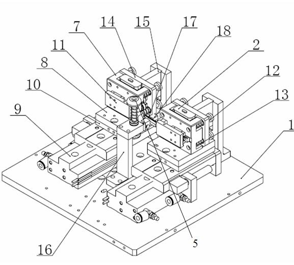
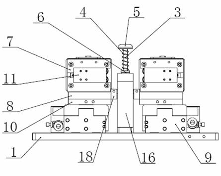
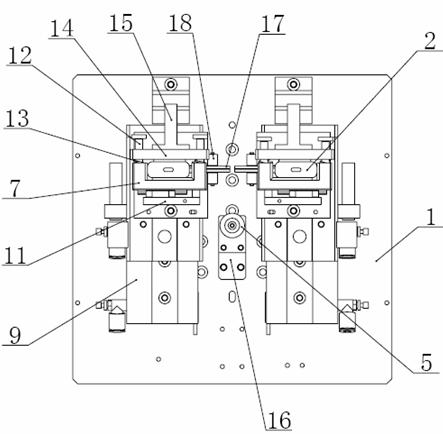
[0020] see Figure 1 to Figure 3 , the present invention provides a power battery laser welding jig, including a bottom plate 1, two welding limit plates 15 are arranged at intervals at the rear end of the bottom plate 1, and each welding limit plate 15 is respectively set in front of There is a slide table cylinder 9, the slide table cylinder 9 is horizontally arranged on the bottom plate 1, and the welding limiting plate 15 is vertically arranged on the bottom plate 1.
[0021] In the present invention, an intermediate plate 10 is arranged on the top of each slide cylinder 9 , and each intermediate plate 10 can slide forward and backward driven by the slide cylinder 9 . The top of each intermediate plate 10 is provided with a clamp bottom plate 8, the front end of the clamp bottom plate 8 is fixed with a battery clamp positioning plate 7, and the front end of the battery clamp positioning plate 7 is provided with a battery side positioning plate 11, and the battery clamp positioning The left and right ends of the plate 7 are respectively fixed with two battery clamp guide shafts 12; the middle outer wall of the battery clamp guide shaft 12 is covered with a battery clamp spring 13, and the rear end of the battery clamp guide shaft 12 is provided with a movable limit plate 14 , the moving limiting plate 14 is located at the rear end of the battery fixture positioning plate 7, the moving limiting plate 14 and the battery fixture positioning plate 7 are connected together by the battery fixture guide shaft 12, and a certain distance is maintained .
[0022] In the present invention, see Figure 1 to Figure 3 , the moving limiting plate 14 can slide back and forth relative to the battery fixture guide shaft 12, and under the action of the battery fixture spring 13, the battery fixture positioning plate 7 and the moving limiting plate 14 are kept in an open state;
[0023] In the present invention, see Figure 1 to Figure 3 There is a U-shaped groove in the middle of the battery fixture positioning plate 7, the U-shaped groove is used to place the power battery 2 that needs to be laser welded, and the shape and size of the U-shaped groove are similar to the power battery 2 correspond to match. In terms of specific implementation, the width of the U-shaped groove is slightly larger than the width of the power battery 2 , and the thickness is slightly smaller than the thickness of the power battery 2 .
[0024] In the present invention, the battery side positioning plate 11 is an L-shaped positioning plate, which can move relative to the width direction of the U-shaped groove of the battery clamp positioning plate 7, and the short side of the L-shaped part can extend into the U-shaped groove, And the power battery 2 in the U-shaped groove is kept in a clamped state, and the clamping and positioning of the power battery 2 in the width direction is well realized.
[0025] It should be noted that, for the present invention, in view of the fact that the intermediate plate 10 can slide forward and backward under the drive of the slide table cylinder 9, the clamp bottom plate 8 on the top of the intermediate plate 10 can slide forward and backward together, so as to be located on the clamp bottom plate 8 The power battery 2 can also slide forward and backward together until the moving limiting plate 14 is in contact with the welding limiting plate 15 at the rear, and the moving limiting plate 14 and the power battery 2 no longer move backward, but The battery fixture positioning plate 7 and the battery fixture guide shaft 12 continue to move backward for a certain distance under the drive of the slide cylinder 9, so that the battery fixture positioning plate 7 can accurately clamp and position the power battery 2 in the thickness direction.
[0026] Since the power battery 2 is firmly clamped under the action of the moving limiting plate 14, the battery clamp positioning plate 7, and the battery side positioning plate 11, the positioning of the power battery 2 in the width and thickness directions can be realized, so it can be kept In the case of battery clamping stability, the operator controls the laser welding equipment to perform various welding operations such as sealing welding of the power battery cover and the battery case, and sealing welding of the power battery liquid injection hole on the power battery 2 to ensure the quality of the battery laser welding .
[0027] see Figure 1 to Figure 3 A battery take-out bracket 16 is arranged between the front ends of the two slide table cylinders 9, and a linear bearing 6 is provided through the top of the battery take-out bracket 16, and a handle guide shaft 3 is provided through the linear bearing 6, so The head of the handle guide shaft 3 has a handle 5, and the outer wall of the handle guide shaft 3 is covered with a helical handle spring 4. It should be noted that, for the present invention, the handle guide shaft 3 passes through the linear bearing 6 and can slide up and down in the vertical direction.
[0028] In the present invention, see Figure 1 to Figure 3 , the two clamp base plates 8 are parallel to each other, and the two clamp base plates 8 are respectively provided with a seesaw seat 18 on opposite ends, and each seesaw seat 18 is hinged with a seesaw plate 17, each The short arm of described seesaw 17 is exposed (as image 3 shown) and between the two seesaw seats 18, the long arm of each seesaw 17 is located at the bottom of the power battery 2 (not shown), and in the natural placement state, the seesaw 17 The height of the long arm is lower than the height of the fixture base plate 8 .
[0029] In the present invention, the seesaw seat 18 is arranged symmetrically with the battery take-out bracket 16. When the end of the short arm of the seesaw 17 moves forward with the clamp bottom plate 8, the end of the short arm of the seesaw 17 moves forward. It can be moved to directly below the handle guide shaft 3 on the battery taking out bracket 16 .
[0030]It should be noted that, for the present invention, under the drive of the slide table cylinder 9, the clamp bottom plate 8 and the moving limiting plate 14 thereon move backwards, contacting the welding limiting plate 15 at the rear, and the power The battery 2 no longer moves backwards, so that the power battery 2 can be accurately positioned, and then laser welding can be performed. After the power battery 2 is laser welded, it is necessary to remove the welded power battery 2. Then, under the drive of the slide cylinder 9, the battery clamp positioning plate 7 and the mobile limit plate 14 on the clamp bottom plate 8 will Move forward, while the seesaw seat 18 and the seesaw 17 move together until it is directly below the handle guide shaft 3 on the battery removal bracket 16, then the worker presses down the handle guide shaft 3 so that the handle guide shaft 3 Press down the end of the short arm of the seesaw 17, then under the action of the principle of the seesaw, the long arm of the seesaw 17 will tilt up, thereby driving the power battery 2 above the long arm of the seesaw 17 to lift up until the power The battery 2 is exposed on the top of the battery fixture positioning plate 7 (higher than the top surface of the battery fixture positioning plate 7), so that it is convenient for the operator to take and unload the power battery 2. The laser-welded power battery 2 is conveniently taken out between the battery fixture positioning plate 7 and the moving limit plate 14.
[0031] After taking out the power battery 2 that has been laser welded, the power battery 2 that needs to be laser welded can be placed between the battery fixture positioning plate 7 and the moving limit plate 14, and continues to be driven by the slide cylinder 9. The clamp bottom plate 8 and the moving limiting plate 14 on it move backwards to contact with the welding limiting plate 15 at the rear to realize accurate positioning of the power battery 2 and perform laser welding on the power battery again. Employees can continuously perform laser welding on the power battery 2 through cyclic operations.
[0032] Since the power battery laser welding jig provided by the present invention can ensure accurate positioning and firm clamping of the power battery, and it is convenient to take and place the power battery, the present invention can greatly improve the efficiency of laser welding tooling for the power battery.
[0033] In addition, the use of the seesaw structure composed of the seesaw seat 18 and the seesaw 17 can ensure that the power battery is completely embedded in the U-shaped groove of the battery fixture positioning plate 7 during welding, and when the power battery 2 is unloaded, By squeezing the seesaw 17 , the power battery 2 can be lifted up, so that the power battery 2 is higher than the top surface of the battery clamp positioning plate 7 , which is convenient for the operator to unload the power battery 2 .
[0034] In summary, compared with the prior art, the present invention provides a power battery laser welding jig, which can maintain the stability of the battery clamping, thereby ensuring the sealing welding of the power battery cover and the battery case, and the power battery liquid injection. The welding reliability of multiple welding fields such as hole sealing welding can improve the quality pass rate of power batteries. At the same time, the welding efficiency is high, which is convenient for improving the production efficiency of power batteries and reducing the overall production cost. It is conducive to wide application in production and has great significance practical significance of production.
[0035] The above is only a preferred embodiment of the present invention, it should be pointed out that, for those of ordinary skill in the art, without departing from the principle of the present invention, some improvements and modifications can also be made, and these improvements and modifications can also be made. It should be regarded as the protection scope of the present invention.

PUM

no PUM

Description & Claims & Application Information

We can also present the details of the Description, Claims and Application information to help users get a comprehensive understanding of the technical details of the patent, such as background art, summary of invention, brief description of drawings, description of embodiments, and other original content. On the other hand, users can also determine the specific scope of protection of the technology through the list of claims; as well as understand the changes in the life cycle of the technology with the presentation of the patent timeline. Login to view more.

Similar technology patents

Methods for treating nicotinic acetylcholine receptor associated diseases

InactiveUS20120148495A1Prevent plasticityMaintain stabilityBiocideSenses disorderNeuroplasticityDisease
Owner:CHILDRENS MEDICAL CENT CORP +1

Stabilizer Bush

Owner:HONDA MOTOR CO LTD

Classification and recommendation of technical efficacy words

  • Maintain stability
  • Improve quality pass rate

Switched mode power converter

Owner:SKYWORKS SOLUTIONS INC
Why Eureka
Try Eureka