Construction Technology of Prestressed Channel Making and Positioning in Post-tensioned Prestressed Beam

A technology of prestressed beams and construction technology, applied in the processing of building materials, structural elements, building components, etc., can solve the problems of difficult to meet the requirements of prestressed channel positioning accuracy, low steel binding accuracy, and unstable steel reinforcement. To achieve the effect of reducing the amount of steel bars, improving the accuracy, and improving the construction efficiency and

Active Publication Date: 2012-02-22
CCCC FIRST HARBOR ENG
View PDF0 Cites 0 Cited by
  • Summary
  • Abstract
  • Description
  • Claims
  • Application Information

AI Technical Summary

Problems solved by technology

[0002] In conventional methods, whether it is the prefabrication of railway T-beams or railway passenger dedicated line box girders, the hole positioning of prestressed tunnels all adopt prefabricated integral grid positioning nets (see attached image 3 ), and then in the process of binding the steel cage of the beam body, the steel bar positioning net is fixed on the steel cage skeleton by binding. Since the steel bar binding accuracy is not high, and the steel bar is not fixed firmly in the form of binding, the positioning of the prestressed channel Accuracy is often difficult to meet the requirements
On the other hand, the construction technique of making holes first and then threading rubber pipes brings considerable difficulty to the pipe threading work. At the same time, this construction method of making positioning holes requires a large amount of steel bars

Method used


Image

  • Construction Technology of Prestressed Channel Making and Positioning in Post-tensioned Prestressed Beam
  • Construction Technology of Prestressed Channel Making and Positioning in Post-tensioned Prestressed Beam
  • Construction Technology of Prestressed Channel Making and Positioning in Post-tensioned Prestressed Beam

Examples


Embodiment Construction

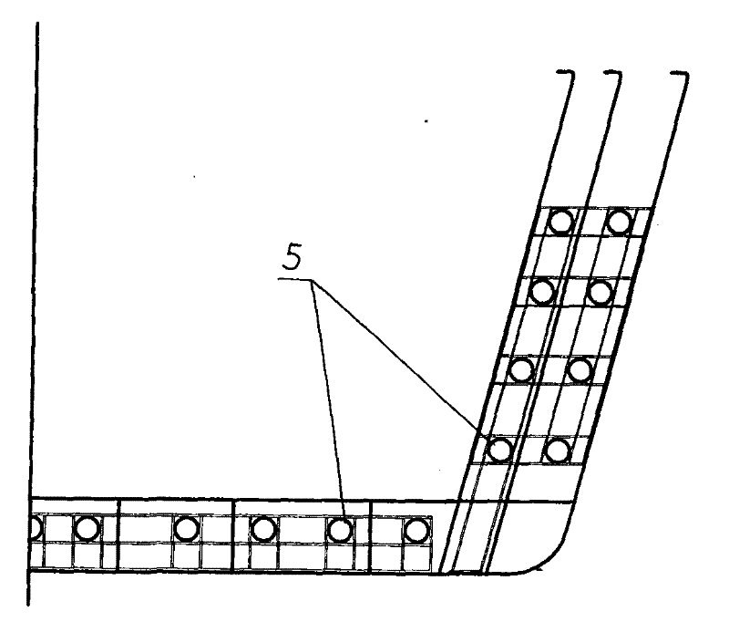
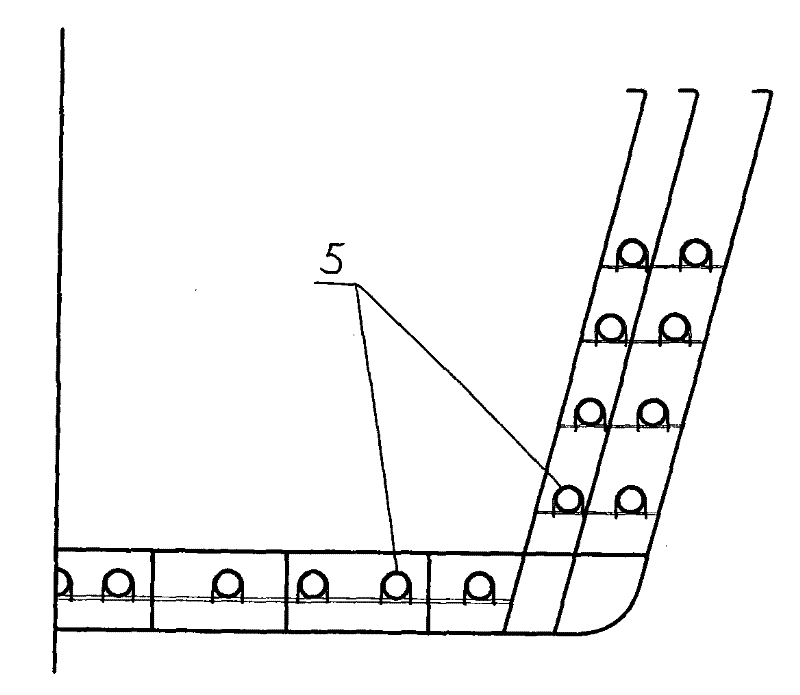
[0023] figure 1 It is an integral grid steel bar positioning net for the positioning of prestressed tunnels in the conventional method, and its steel bars are densely arranged, while the construction technology of the present invention uses positioning ribs for positioning. Therefore, from figure 1 , figure 2 It can be seen from the comparison that this construction technology significantly reduces the amount of steel bars compared with the conventional method.

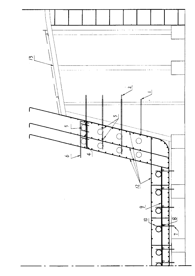
[0024] Reference to the construction technology of the prestressed channel hole making and positioning of the post-tensioned prestressed beam of the present invention image 3 , Figure 4 shown, including the following steps:

[0025] a. According to the position coordinate table of the prestressed reserved hole, process and manufacture the horizontal positioning caliper 6 of the web hole and the vertical positioner of the bottom plate hole. The vertical locator of the bottom plate hole is fixed with a vertical ...


PUM


Abstract

The invention discloses a post-tensioned prestressed beam prestressed hole-making positioning construction process, the process is: pre-fixing the vertical positioning pipe of the web channel and the horizontal positioning tube of the bottom plate channel on the steel bar binding mold; The vertical positioning rib of the web channel extending to the steel cage frame of the box girder is pierced through the vertical positioning pipe of the plate channel; the vertical positioner of the bottom plate channel extending to the steel cage skeleton of the box girder is connected in the horizontal positioning tube of the channel of the bottom plate; The bottom level support ribs are welded on the steel cage frame of the box girder; the rubber tube is placed on the web bottom level support ribs, and the rubber tube is positioned laterally with the web channel lateral positioning caliper and fixed by welding U-shaped clips; Set up the bottom level support ribs on the vertical positioning mark of the locator, weld the bottom level support ribs to the steel cage frame of the box girder, and lay rubber tubes at the intersection of the bottom level support ribs and the horizontal positioning ribs of the bottom plate channel And weld the U-shaped card to fix it.

Description

technical field [0001] The invention relates to a construction technique of a post-tensioned prestressed beam, in particular to a construction technique for making and positioning a prestressed channel of a post-tensioned prestressed beam. Background technique [0002] In conventional methods, whether it is the prefabrication of railway T-beams or railway passenger dedicated line box girders, the hole positioning of prestressed tunnels all adopt prefabricated integral grid positioning nets (see attached image 3 ), and then in the process of binding the steel cage of the beam body, the steel bar positioning net is fixed on the steel cage skeleton by binding. Since the steel bar binding accuracy is not high, and the steel bar is not fixed firmly in the form of binding, the positioning of the prestressed channel Accuracy is often difficult to meet the requirements. On the other hand, the construction technology of making holes first and then wearing rubber pipes brings conside...

Claims


Application Information

Patent Timeline
Patent Type & Authority Patents(China)
IPC IPC(8): E04C5/10E04G21/02
Inventor 李一勇梁萌李增军康建洋董光辉秦观魏颂张峰甲
Owner CCCC FIRST HARBOR ENG
Why Eureka
Try Eureka