
Electric control signal reflection fan clutch

A signal reflection and clutch technology, applied in clutches, fluid clutches, machines/engines, etc., can solve problems such as inaccurate speed, unfavorable energy saving and environmental protection, and delays in central processing unit adjustment, so as to ensure accuracy and save production and assembly costs. Effect

Inactive Publication Date: 2011-04-06
SUZHOU RISING AUTO PARTS
View PDF3 Cites 5 Cited by
  • Summary
  • Abstract
  • Description
  • Claims
  • Application Information

AI Technical Summary

Problems solved by technology

The disadvantage of this structure is: because the electromagnetic control valve switch assembly contains a magnetic coil, and the Hall principle adopted by the fan speed measurement assembly also contains a permanent magnet, when the speed is measured, the strong magnetic field generated by the energized magnetic coil will It has a certain impact on the magnetic field signal received by the Hall element, causing the magnetic signal received by it to weaken, and the Hall element cannot receive the normal magnetic signal, resulting in inaccurate measured speed, and the speed signal data output to the central processor Mistakes lead to a delay in the adjustment of the central processing unit or no adjustment at all, consuming excess energy of the engine, which is not conducive to energy saving and environmental protection

Method used


Image

  • Electric control signal reflection fan clutch
  • Electric control signal reflection fan clutch
  • Electric control signal reflection fan clutch

Examples


Embodiment Construction

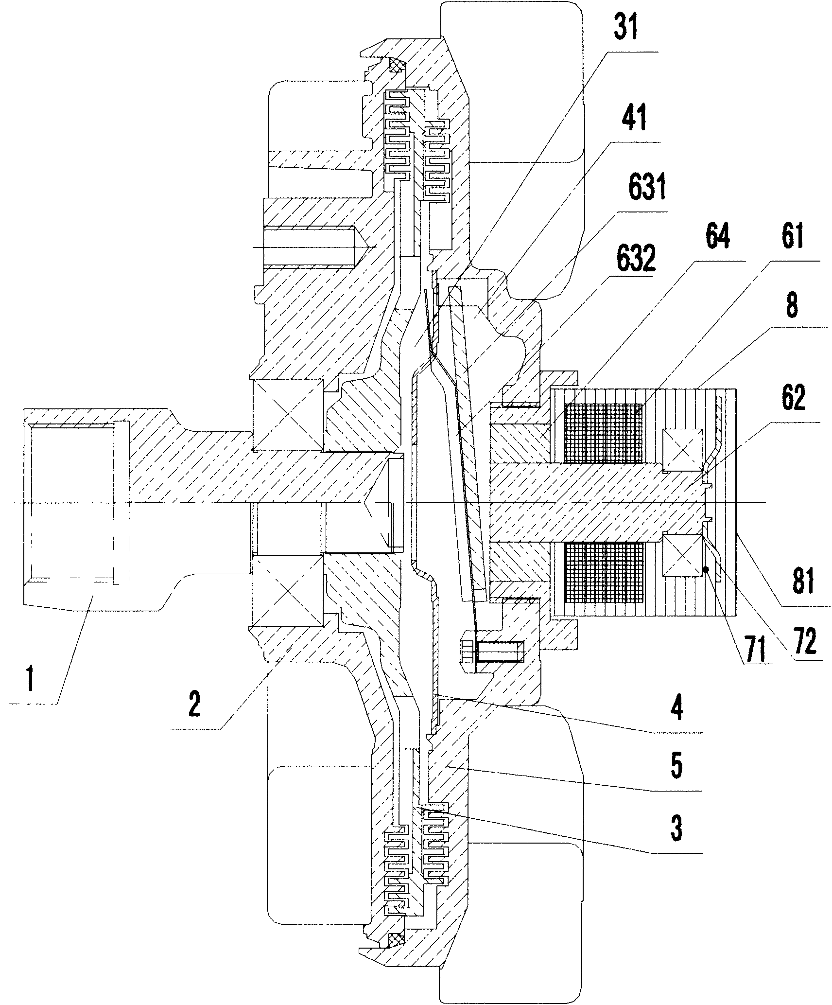
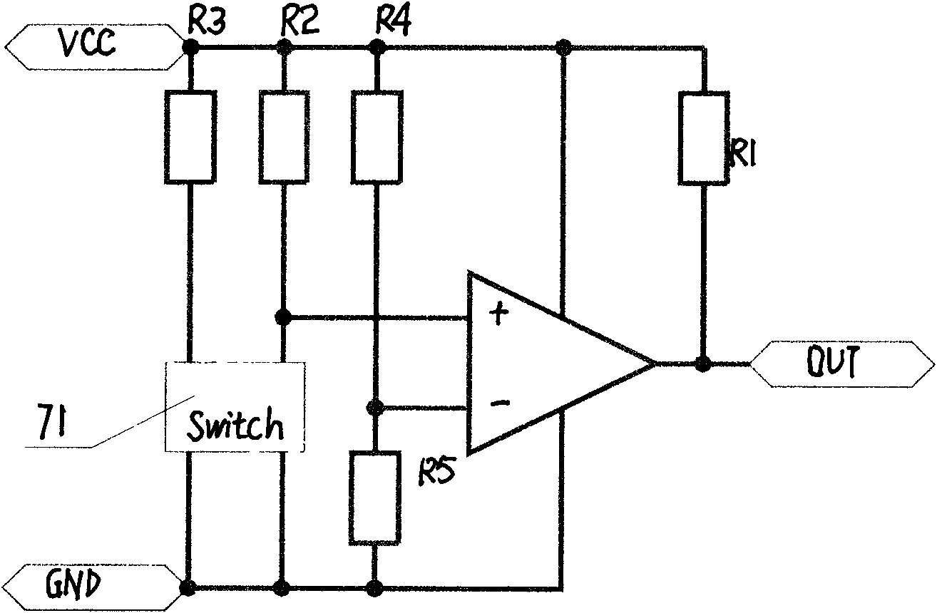
[0017] In view of the present invention, a preferred embodiment is now given and explained in conjunction with the drawings: the electric control signal reflection fan clutch includes a driving shaft 1, a housing 2, a driving plate 3, a driven plate 4, an end cover 5, an electromagnetic control Switch, fan speed test kit, see figure 1 , figure 2 , image 3 ,in:

[0018] The drive shaft 1, which rotates synchronously with the engine shaft, has a housing 2 fixed on the drive shaft 1 through bearings; the drive shaft 1 is fixedly connected with the drive plate 3 that rotates with the drive shaft; the end cover 5 is located at the front end of the drive plate 3 , and fixed together with the housing 2 by screws, the end cover 5 and the housing 2 are correspondingly provided with tooth grooves, the front and rear tooth saws on the active plate 3 mesh with the tooth grooves on the end cover 5 and the housing 2 respectively; Driven plate 4 is positioned between active plate 3 and ...


PUM


Abstract

The invention relates to an electric control signal reflection fan clutch which comprises a driving shaft, a shell, a driving plate, a follower plate, a photoelectric induction type fan speed test component and a central processing unit, wherein the shell is installed on the driving shaft through a bearing; the driving plate is fixed on the driving shaft; the follower plate is fixed on an end cover; the fan is installed on the follower plate; the end cover and the shell are fixed integrally; an oil storing cavity and a working cavity are arranged between the end cover and the shell; the oil storing cavity and the working cavity are communicated by an oil inlet and an oil return hole; the oil inlet is controlled by an electromagnetic control switch to be opened and closed; the photoelectric induction type fan rotate speed test component tests the fan rotate speed; and the central processing unit receives the test signals. The fan rotate speed test component with the structure is unaffected by the magnetic field of an electromagnetic switch, and has accurate speed measuring, energy saving and environmental protection.

Description

technical field [0001] The invention relates to a silicon oil fan clutch, in particular to a silicon oil fan clutch controlled by an electric control signal. Background technique [0002] The silicone oil fan clutch uses silicone oil as a medium to transmit torque by utilizing the high viscosity of silicone oil. Using the temperature of the air behind the radiator, the disengagement and engagement of the fan clutch is automatically controlled by a temperature sensor. When the temperature is low, the silicone oil does not flow, the fan clutch disengages, and the fan speed slows down, basically idling. When the temperature is high, the viscosity of the silicone oil makes the fan clutch engage, so the fan and the water pump shaft rotate together to regulate the temperature of the engine. [0003] The disadvantage of this kind of silicon oil fan clutch that is only adjusted by a temperature sensor is that when the fan speed reaches a certain speed and the temperature drops bel...

Claims


Application Information

Patent Timeline
Patent Type & Authority Applications(China)
IPC IPC(8): F01P7/04F16D48/06F16D35/00
Inventor 龚达锦严刚秦星勇
Owner SUZHOU RISING AUTO PARTS
Learn More