Continuous oil supply device

An oil supply device and oil cup technology, used in engine components, engine lubrication, mechanical equipment, etc., can solve the problems of high cost, insufficient oil supply, and many requirements for working conditions, and achieve simple control and oil supply. Continuous, simple structure effects

Inactive Publication Date: 2011-04-06
ZHEJIANG UNIV
View PDF5 Cites 1 Cited by
  • Summary
  • Abstract
  • Description
  • Claims
  • Application Information

AI Technical Summary

Problems solved by technology

The above-mentioned oil supply device has insufficient oil supply, high cost or more requirements on working conditions

Method used


Image

  • Continuous oil supply device
  • Continuous oil supply device
  • Continuous oil supply device

Examples


Embodiment Construction

[0019] The present invention will be further described below in conjunction with the accompanying drawings and specific examples.

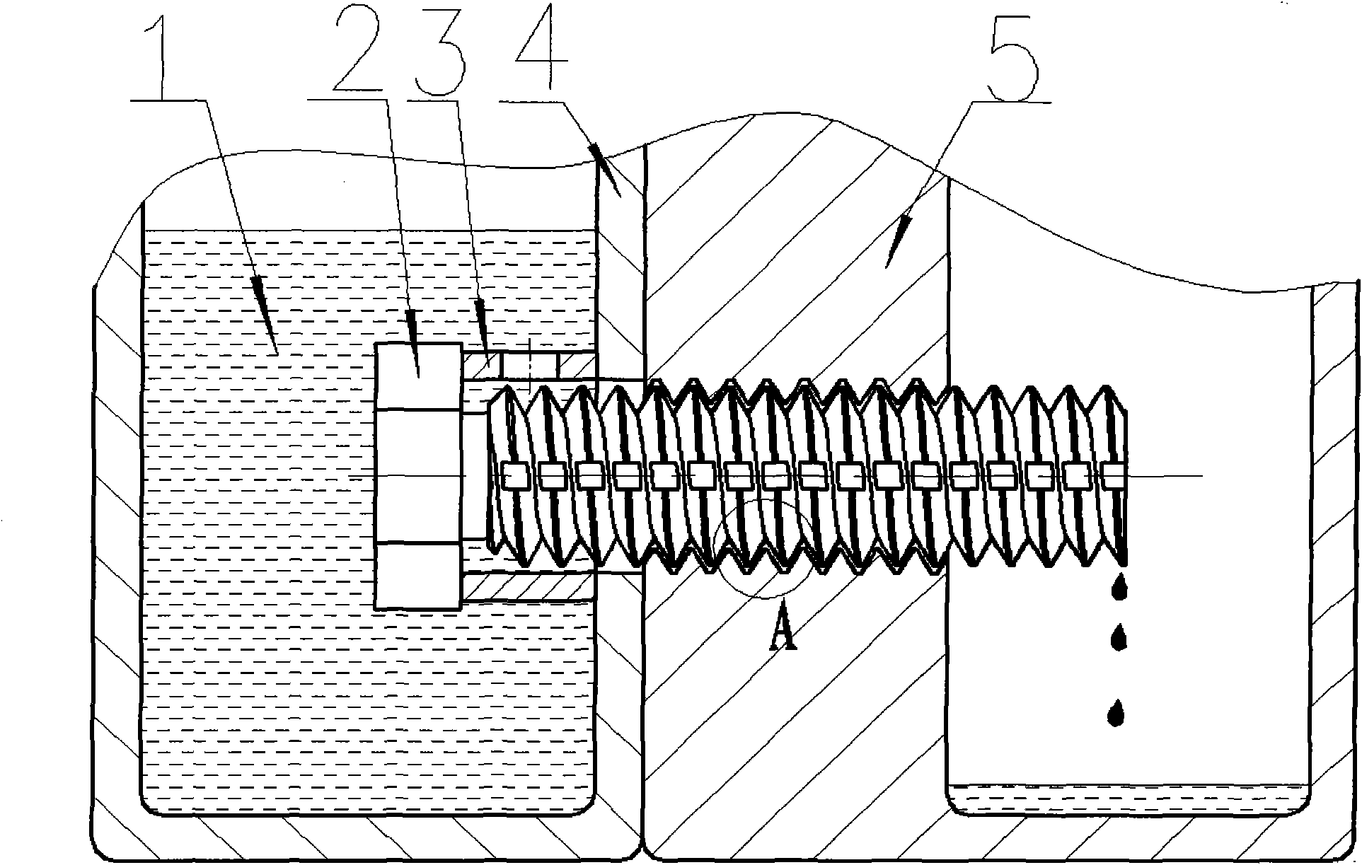
[0020] Such as figure 1 , figure 2 As shown, a slotted screw 2 is used to connect the side wall of the oil cup or oil tank 4 containing lubricating oil 1 and the side wall of the device 5 requiring lubricating oil, and the slotted screw 2 is equipped with a radial side wall opening. The retaining ring 3 of the small hole, and the screw head is immersed in the lubricating oil in the oil cup or oil tank, the radial side wall hole of the retaining ring 3, the screw groove and the thread engagement gap are all oil passages.

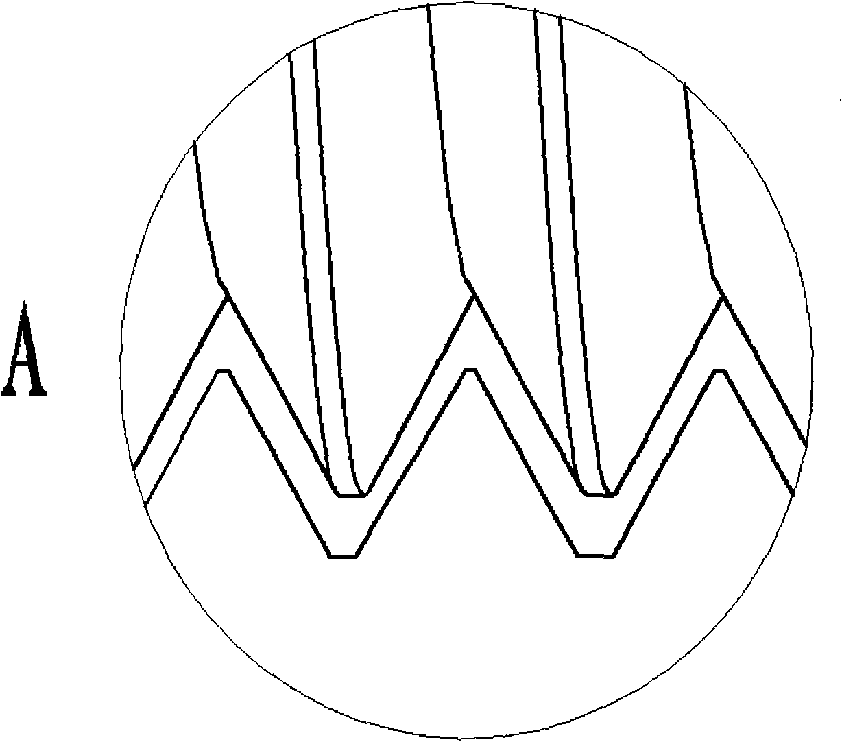
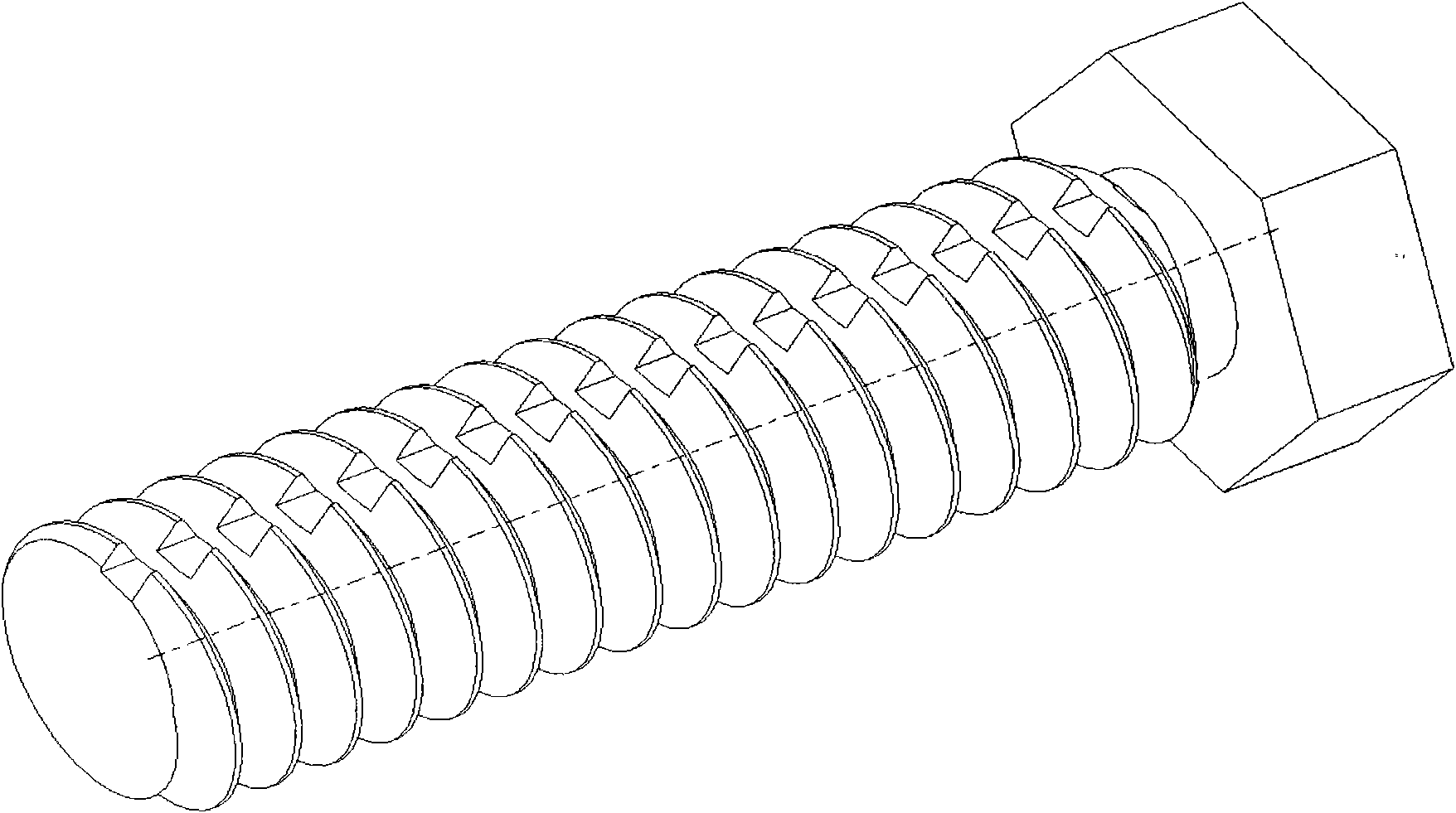
[0021] Such as image 3 , Figure 4 As shown, the groove of the screw rod is a straight groove or a spiral groove. When the slot is a straight-through slot, if the slotted threaded rod is M20mm, the slot width ranges from 0.1 to 1mm. When the groove is a helical groove, the helical groove and the thread of the screw are in ...


PUM


Abstract

The invention discloses a continuous oil supply device, which is characterized in that the side wall of an oil cup or an oil tank containing lubricating oil and the side wall of a device needing lubricating oil is connected by a screw with slots; the screw is provided with a check ring with radial side wall with small holes; the head of the screw is soaked in the lubricating oil in the oil cup or the oil tank; and oil ducts are arranged in the positions of the holes on the radial side wall of the check ring, the slots on the screw and the thread engagement clearance. The device can support the lubricating oil to flow into the device needing lubricating oil through the slots on the screw and the thread engagement clearance. The oil supply can be changed as the length of thread engagement is changed. When screwing the threads, the external thread pre-screws the internal thread, thus stopping oil supply.

Description

technical field [0001] The invention relates to an oil supply device, in particular to a continuous oil supply device. Background technique [0002] The continuous oil supply device is known in the prior art, and there are forms such as wick lubrication, drip lubrication, oil ring lubrication, splash lubrication and pressure circulation lubrication. The above-mentioned oil supply device has insufficient oil supply, high cost or more requirements on working conditions. [0003] If grooves are directly made on the screw connected to the device to be lubricated, the lubricating oil enters the device to be lubricated through the radial side wall holes, grooves, and thread engagement gaps of the retaining ring. The structure is simple, and the oil flows in the closed space groove There is no risk of clogging, and there are no special requirements for working conditions such as speed, load, and oil quality: the oil supply can be changed by changing the thread engagement gap; and ...

Claims


Application Information

Patent Timeline
Patent Type & Authority Applications(China)
IPC IPC(8): F16N7/00
Inventor 李慧黎伟汪久根
Owner ZHEJIANG UNIV
Why Eureka
Try Eureka