Dehumidifier

A dehumidifier and chassis technology, which is used in household heating, lighting and heating equipment, and prevention of condensation , to achieve the effect of reducing vibration and noise, uniform force, and increasing water intake

Inactive Publication Date: 2011-04-06
LG ELECTRONICS (TIANJIN) APPLIANCES CO LTD
View PDF0 Cites 13 Cited by
  • Summary
  • Abstract
  • Description
  • Claims
  • Application Information

AI Technical Summary

Problems solved by technology

[0016] In the dehumidifier of the prior art, the evaporator and the condenser are arranged side by side in parallel, and the condensed water flowing down from the evaporator is directly discharged into the water tank and then poured out. This part of the condensed water after contacting the evaporator has a rela

Method used


Image

  • Dehumidifier
  • Dehumidifier
  • Dehumidifier

Examples


Example Embodiment

[0037] The present invention is described in detail below with reference to accompanying drawing and embodiment:

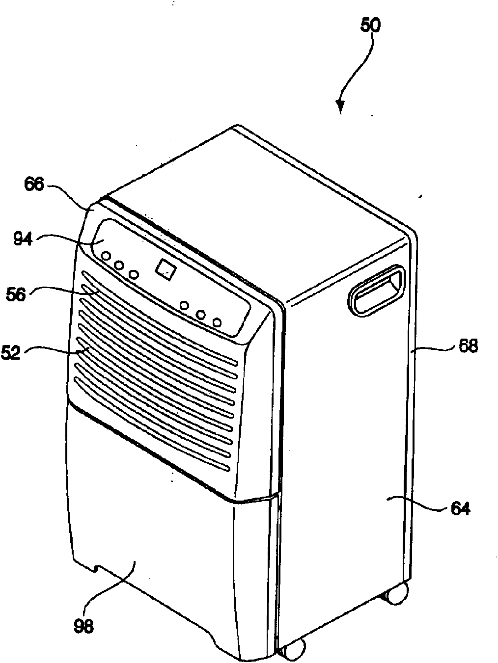
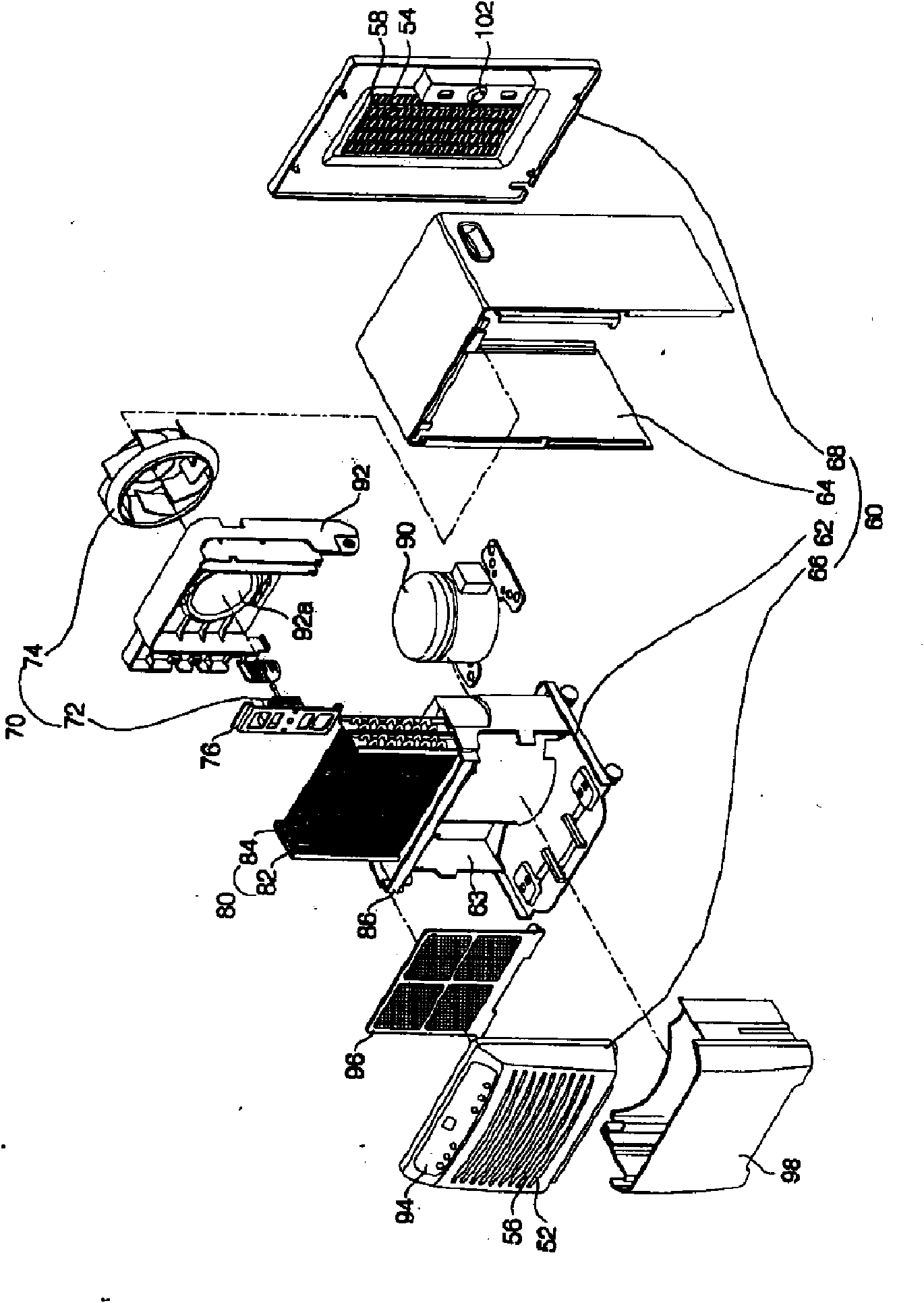
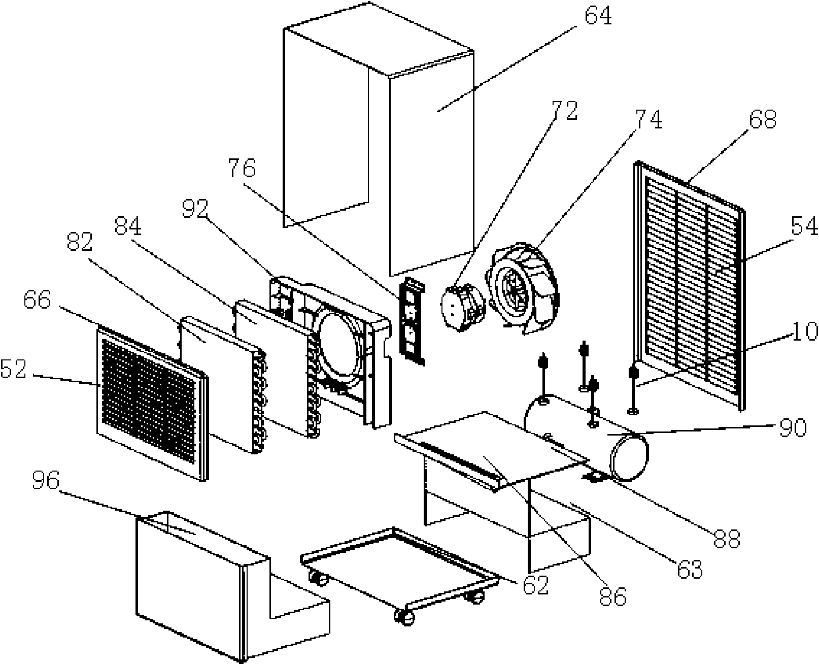
[0038] image 3 is a schematic structural view of the dehumidifier of the present invention; Figure 4 is a side view of the interior of the dehumidifier of the present invention; Figure 5 It is a structural schematic diagram of the suspension and fixing method of the compressor in the dehumidifier of the present invention; Image 6 It is a partial enlarged view of the fixing position of the connecting rod and the compressor bracket in the dehumidifier of the present invention; Figure 7 It is a partially enlarged view of the damping spring on the connecting rod in the dehumidifier of the present invention; Figure 8 It is a schematic diagram of the interior rear side of the dehumidifier of the present invention.

[0039] like Figure 3 to Figure 8 As shown, in the dehumidifier of the present invention, the cabinet forms the appearance of the dehumidifier, a...


PUM


Abstract

The invention relates to a dehumidifier which comprises a case, an evaporator, a condenser, a fan and a baffle plate, wherein a water collecting disk horizontally extends to the direction of an air outlet of the dehumidifier to form a supporting plate; a compressor which is arranged transversely is hung below the supporting plate through a plurality of connecting rods; the compressor is not in contact with the case, the supporting plate and the baffle plate; and a damping spring is arranged on each connecting rod, i.e. the damping spring is connected to each connecting rod to become part of each connecting rod. When the dehumidifier operates, the vibration generated by the compressor can not be directly transferred to a chassis and can be transferred to the case to generate vibration noise, and the damping spring arranged on each connecting rod and a damping rubber gasket arranged at the fixing part of each connecting rod and a compressor bracket can fully reduce the vibration of the compressor, thereby lowering the vibration and the noise when the dehumidifier operates.

Description

technical field [0001] The invention belongs to the technical field of dehumidifiers, and in particular relates to a support plate formed by extending a water receiving tray, and a horizontally placed compressor is suspended under the support plate through a connecting rod, so that the compressor is in a suspended state, and the water receiving capacity is increased. While reducing the vibration noise of the dehumidifier. Background technique [0002] Generally speaking, the dehumidifier introduces the humid air in the room into the inside of the chassis, reduces the humidity through a heat exchanger composed of an evaporator and a condenser with refrigerant flow, and then discharges the dehumidified air into the room to reduce the humidity. Device for indoor humidity purposes. [0003] figure 1 is an external schematic diagram of a dehumidifier in the prior art; figure 2 It is a structural decomposition schematic diagram of a dehumidifier in the prior art. [0004] lik...

Claims


Application Information

Patent Timeline
IPC IPC(8): F24F1/02F24F13/22F24F13/24
Inventor 杨瑱万兴朱百发
Owner LG ELECTRONICS (TIANJIN) APPLIANCES CO LTD
Why Eureka
Try Eureka