
Neutral point direct current (DC) magnetic bias suppression resistor of transformer

A technology of DC bias suppression and transformer neutral point, applied in the direction of resistors, resistor parts, resistor shells/packaging shells/potting, etc., can solve the problem of large short-circuit current, large impact on primary equipment, and complex system impact and other problems, to achieve the effect of suppressing the influence of DC bias, protecting against overvoltage damage, and simple operation mode

Active Publication Date: 2011-04-06
SHANGHAI MUNICIPAL ELECTRIC POWER CO +3
View PDF4 Cites 7 Cited by
  • Summary
  • Abstract
  • Description
  • Claims
  • Application Information

AI Technical Summary

Problems solved by technology

[0002] At present, there are some methods to suppress DC current at home and abroad, such as the reverse current compensation method, but the control is complicated, the reliability is poor during operation, and it is easy to malfunction; High, the short-circuit current is large, and the influence of the device itself and the system is also relatively complicated, and it cannot be installed at the same time as the small reactance at the neutral point that limits the single-phase short-circuit current

Method used


Image

  • Neutral point direct current (DC) magnetic bias suppression resistor of transformer
  • Neutral point direct current (DC) magnetic bias suppression resistor of transformer
  • Neutral point direct current (DC) magnetic bias suppression resistor of transformer

Examples


Embodiment Construction

[0026] The present invention will be described in detail below in conjunction with the accompanying drawings and embodiments.

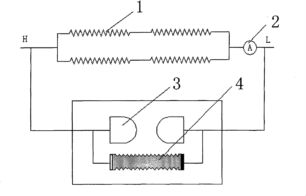
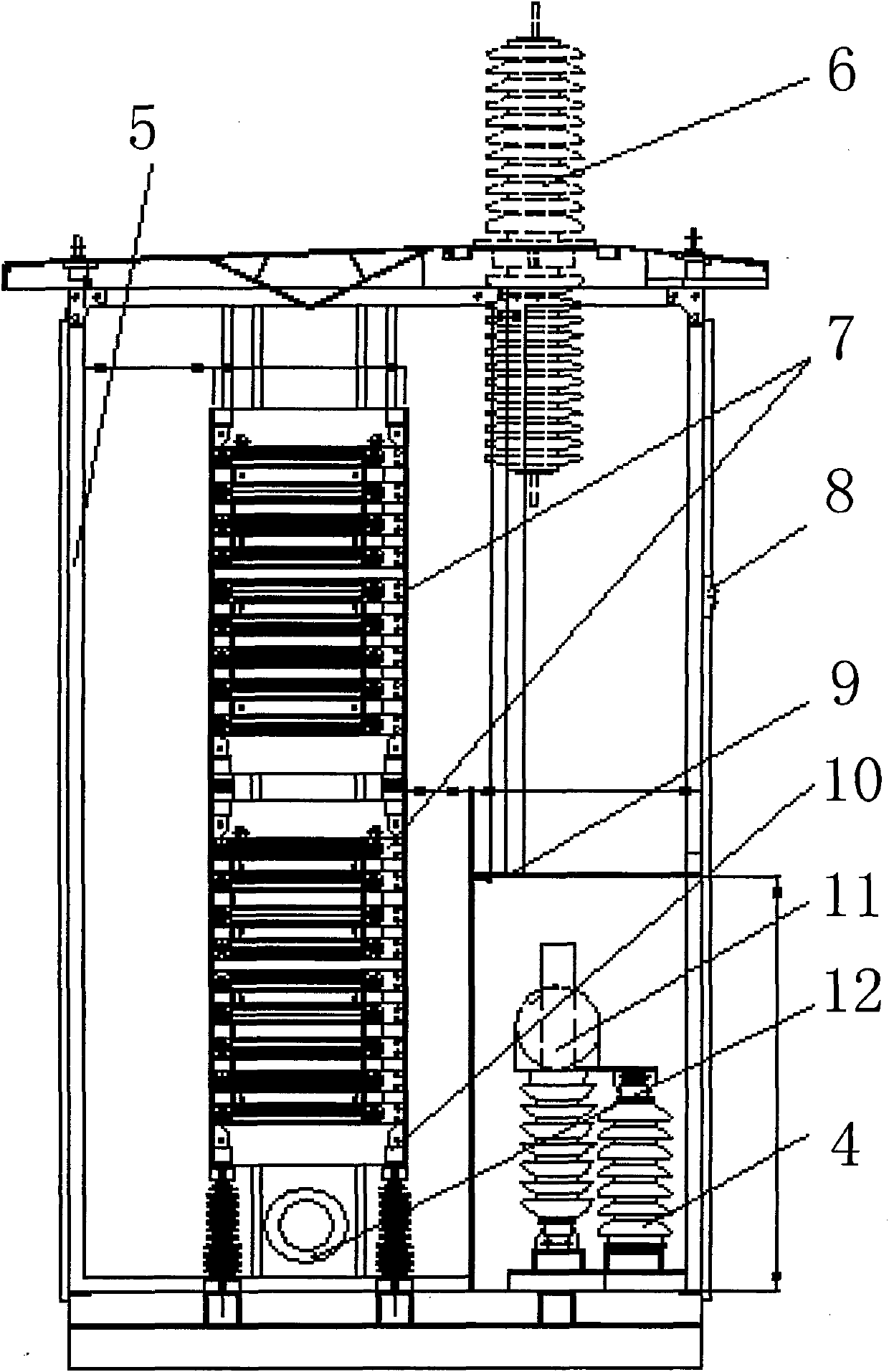
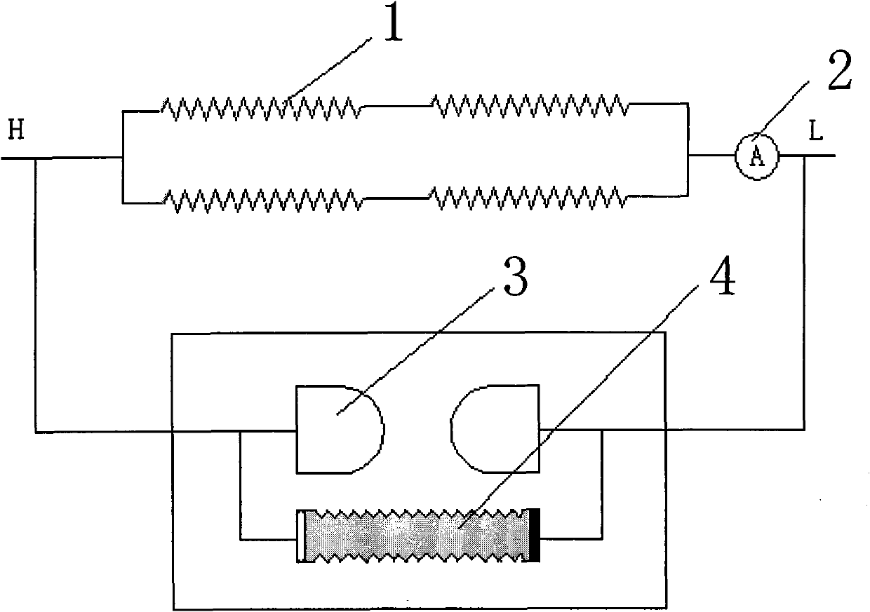
[0027] see figure 1 and figure 2 , the present invention provides a transformer neutral point DC bias suppression resistor, which consists of a resistor 1, a current monitor 2, a graphite ball 3, a lightning arrester 4, a box 5, an incoming line bushing 6, a resistor 7, and a current monitoring Meter 8, insulation isolation chamber 9, insulation support frame 10, graphite ball gap 11 and outlet bushing 12.

[0028] Among them, the resistor 1 , the graphite ball 3 , the lightning arrester 4 , the insulating isolation chamber 9 , and the insulating support frame 10 are all arranged in the box body 5 . The resistor 1 includes a plurality of resistors 7, the resistors 7 are formed by winding nickel-chromium alloy or nickel-chromium-aluminum alloy resistance sheets and welding them in series, the openings on the resistance sheets are connected in series...


PUM


Abstract

The invention relates to a neutral point direct current (DC) magnetic bias suppression resistor of a transformer. The neutral point (DC) magnetic bias suppression resistor comprises a plurality of resistances arranged in a tank body, a current monitor and a pair of graphite spheres, wherein each resistance is formed by winding, welding and connecting resistance chips made of nickel chromium alloy or nickel chromium aluminum alloy in serials, each resistor chip is provided with a hole and is connected in series to a connecting rod, the connecting rod is fixed on an insulating support frame, and both ends of the resistor are connected in parallel with a pair of the graphite sphere gaps; the resistor is formed by connecting the plurality of the resistances in serials; and the current monitor comprises a current monitoring meter. By additionally arranging small resistances to the neutral point of the transformer, the resistor of the invention can effectively restrict the direct current flowing through the neutral point of the master transformer and has small and controllable influence on a transformer body and the system. Besides, the resistor of the invention has simple operating mode, can be connected with small reactors at the neutral point in serials and simultaneously ensures that the problem of restrictions on direct current and single-phase short-circuit current is solved. By connecting small resistances in series to the neutral point of the transformer, the invention has the advantages that the influence of DC magnetic bias can be effectively inhibited and the transformer is prevented from the increase of vibration, noise and loss caused by magnetic bias.

Description

technical field [0001] The invention relates to a transformer in a power system, in particular to a transformer neutral point grounding resistor for suppressing DC bias in the power system, in particular to a transformer neutral point DC bias suppressing resistor. Background technique [0002] At present, there are some methods to suppress DC current at home and abroad, such as the reverse current compensation method, but the control is complicated, the reliability is poor during operation, and it is easy to malfunction; High, the short-circuit current is large, and the influence of the device itself and the system is relatively complicated, and it cannot be installed at the same time as the neutral point small reactance that limits the single-phase short-circuit current. [0003] In view of this, seeking a DC bias suppression resistor at the neutral point of a transformer has become a goal pursued by those skilled in the art. Contents of the invention [0004] The task o...

Claims


Application Information

Patent Timeline
Patent Type & Authority Applications(China)
IPC IPC(8): H01C13/02H01C1/014H01C1/02H01F27/34
Inventor 李福兴周行星黄华陈俊杰
Owner SHANGHAI MUNICIPAL ELECTRIC POWER CO
Learn More