A permanent magnet governor cooling system

A permanent magnet speed governor and cooling system technology, applied in cooling/ventilation devices, electrical components, electromechanical devices, etc., can solve the problem of inability to conduct conductor rotors to adjust heat dissipation capacity, increase equipment installation and use space, and corrosion of permanent magnet materials and other parts and other problems, to achieve the effect of wide cooling temperature range, convenient production and transformation, and simple installation method

Inactive Publication Date: 2018-12-14
武汉钢铁有限公司
View PDF7 Cites 2 Cited by
  • Summary
  • Abstract
  • Description
  • Claims
  • Application Information

AI Technical Summary

Problems solved by technology

[0006] 1. Generally, liquid cooling and air cooling are passive heat dissipation, which are easily restricted by the ambient temperature and the working conditions of the permanent magnet governor, and cannot adjust the heat dissipation capacity according to the heat generation of the conductor rotor;
[0007] 2. The liquid-cooled heat dissipation method will cause the medium to contact the conductor rotor, which may cause corrosion of permanent magnet materials and other components, and reduce the insulation of the device;
[0008] 3. Liquid cooling requires the use of water pumps and radiators in order to ensure the cooling effect. In particular, high-power permanent magnet governors also need refrigeration devices to reduce the temperature of cooling water, which increases the space for equipment installation and use.
[0009] It can be seen that most of the cooling methods of the existing permanent magnet governor cannot actively adjust the heat dissipation capacity, and the liquid cooling method increases the complexity of the internal structure of the permanent magnet governor. In order to ensure the cooling effect, additional equipment is required, thereby increasing Larger equipment operating space

Method used


Image

  • A permanent magnet governor cooling system
  • A permanent magnet governor cooling system
  • A permanent magnet governor cooling system

Examples


Embodiment Construction

[0039]The following will clearly and completely describe the technical solutions in the embodiments of the present invention with reference to the accompanying drawings in the embodiments of the present invention. Obviously, the described embodiments are only some, not all, embodiments of the present invention. Based on the embodiments of the present invention, all other embodiments obtained by persons of ordinary skill in the art without making creative efforts belong to the protection scope of the present invention.

[0040] First, an embodiment of the present invention provides a cooling system for a permanent magnet governor.

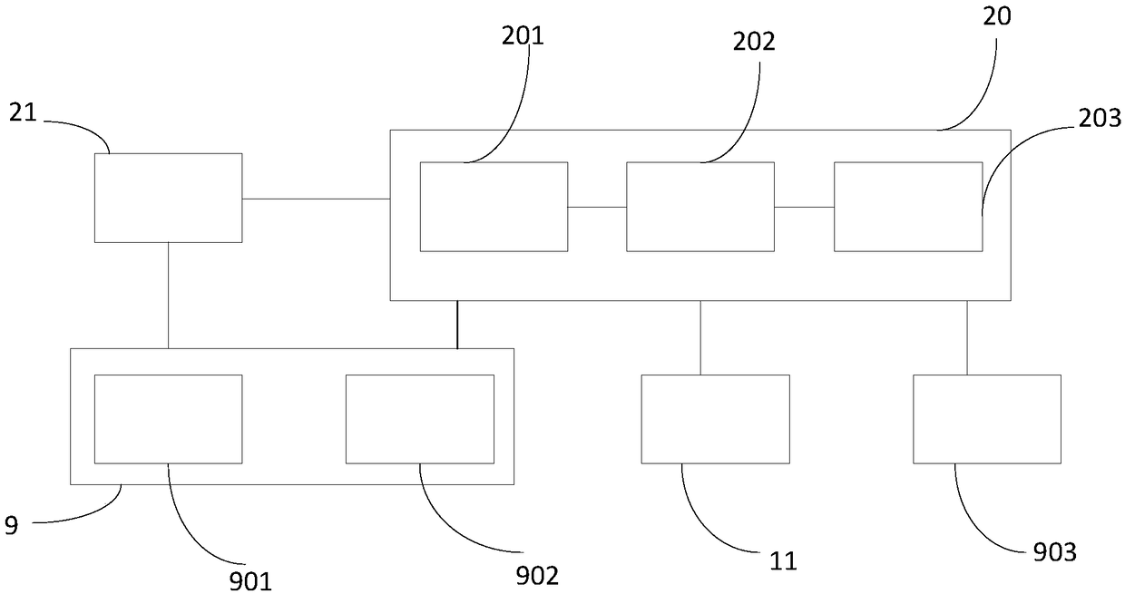
[0041] figure 1 It is a schematic frame diagram of a permanent magnet governor cooling system according to an embodiment of the present invention, see figure 1 , the system includes a peltier cooling assembly 9 , a first temperature sensor 11 , a second temperature sensor 903 and a processing unit 20 .

[0042] The semiconductor refrigeration asse...


PUM


Abstract

The invention particularly relates to a cooling system of a permanent magnet governor. A power supply and a processing unit of the system are connected with a semiconductor refrigeration module, the cooling end of the semiconductor refrigeration module is used for cooling the conductor rotor disk of the permanent magnet speed governor, the heating end of the semiconductor refrigeration module is used for the heat derivation generated by the semiconductor refrigeration module, the first temperature sensor and the second temperature sensor are capable of transmitting the temperature informationof the eddy current side of the conductor rotor disk of the permanent magnet speed governor and the temperature information of the heating end of the semiconductor refrigeration module to the processing unit, the detection processor of the processing unit receives and processes the temperature information to obtain the real-time temperature of the vortex side of the conductor rotor disk of the permanent magnet speed governor and the real-time temperature of the heating end of the semiconductor refrigeration module, The controller compares the above temperature with a preset suitable temperature, and controls the refrigeration capacity of the refrigeration end of the semiconductor refrigeration module and the heat generation amount of the heating end of the semiconductor refrigeration module. The invention relates to an active cooling method.

Description

technical field [0001] The invention belongs to the technical field of speed adjustment cooling, and in particular relates to a cooling system for a permanent magnet governor. Background technique [0002] The permanent magnet speed governor adopts the magnetic field non-contact transmission mode, which has many advantages such as high reliability, strong adaptability, good vibration isolation effect, long service life, soft start and overload protection, and is widely used in high-power fans and pumps. transmission. [0003] Generally, the permanent magnet governor drives the conductor rotor to rotate through the motor, and the conductor rotor cuts the magnetic field of the permanent magnet rotor to generate an induced current, thereby generating electromagnetic force to drive the permanent magnet rotor to rotate. When the permanent magnet governor is in continuous operation, the induced current of the conductor rotor will generate a lot of heat. On the one hand, the heat ...

Claims


Application Information

Patent Timeline
Patent Type & Authority Applications(China)
IPC IPC(8): H02K9/00H02K11/25
CPCH02K9/00H02K11/25
Inventor 邓攀刘洋喻昉李华李恒山胡念慈魏从艳
Owner 武汉钢铁有限公司
Why Eureka
Try Eureka