
Pre-bunching high-power gyro traveling wave tube amplifier

A technology for traveling wave tube amplifiers and amplifying sections, which is applied to traveling wave tubes, discharge tubes, and time-of-flight electron tubes to achieve high stability, reduce cooling technology requirements, and improve overall efficiency.

Inactive Publication Date: 2011-04-06
INST OF ELECTRONICS CHINESE ACAD OF SCI
View PDF0 Cites 16 Cited by
  • Summary
  • Abstract
  • Description
  • Claims
  • Application Information

AI Technical Summary

Problems solved by technology

Usually, the end of the distributed loss section of the gyrotron amplifier needs to lose about 5% of the output power of the device. These factors limit the output power level of the device

Method used


Image

  • Pre-bunching high-power gyro traveling wave tube amplifier
  • Pre-bunching high-power gyro traveling wave tube amplifier
  • Pre-bunching high-power gyro traveling wave tube amplifier

Examples


Embodiment Construction

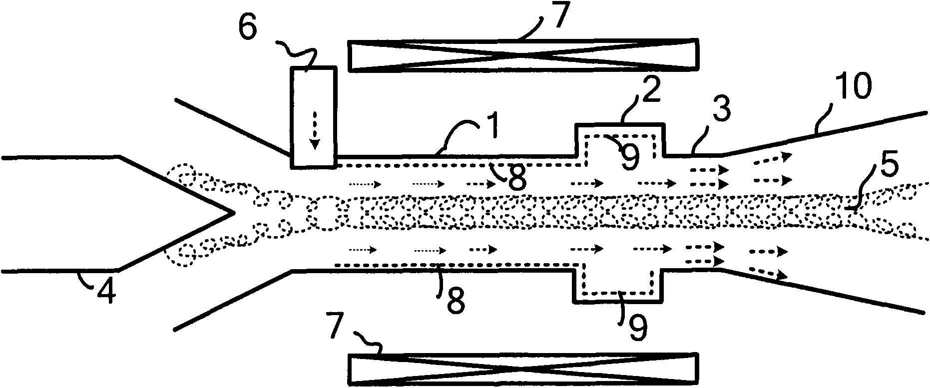
[0025] The pre-clustered high-power cyclotron traveling wave tube amplifier of the present invention has a three-stage structure:

[0026] The first section is a linear amplification section, which uses distributed loss to load the metal waveguide. The metal waveguide is usually a circular waveguide, and the inner wall of the waveguide is coated with a loss material or loaded with a layer of loss ceramics to form a distributed loss. The linear linear amplification section loaded with distributed loss has the advantage of high stability, and can ensure that the cyclotron beam obtains sufficient pre-modulation of the input power.

[0027] The second section is the inertial drift section, and the overmode waveguide is loaded with heavy loss. The heavily loss-loaded overmode waveguide can fully absorb various oscillation modes, and provide an inertial grouping space of approximately zero field for the pre-modulated electron beam, so that it can obtain excellent grouping character...


PUM

PropertyMeasurementUnit
Radiusaaaaaaaaaa
Radiusaaaaaaaaaa
Radiusaaaaaaaaaa

Abstract

The invention discloses a pre-bunching high-power gyro traveling wave tube amplifier and relates to a microwave source device technology, comprising three sections: a linear amplifying section which adopts loss loading metal waveguide; an inertial drifting section which adopts heavy loss loading over-mode waveguide to provide an inertial bunching space approximating zero field for a bunching electron beam; and a nonlinear amplifying section which adopts smooth metal waveguide, wherein the gyro electron beam is fully modulated by driving power in the linear section; the modulated electron beam obtains good bunching characteristic according to inertia in the inertial drifting section; and the electron beam with good bunching vehemently reacts with an operating mode in the nonlinear amplifying section and transforms transverse kinetic energy to microwave energy to obtain high-energy microwave output. Both the linear amplifying section and the inertial drifting section are loss loops to guarantee the stability of the device; and the nonlinear amplifying section adopts the pre-bunching electron beam to work, and has the advantages of high power, high stability, and high efficiency.

Description

technical field [0001] The invention relates to the technical field of microwave source devices, and relates to a gyrotron amplifier using a grouping section. Background technique [0002] In the late 1950s, the principle of electron cyclomaser interaction was discovered, and high-energy microwave sources based on this principle have been studied in depth both theoretically and experimentally. These high-energy microwave sources are used in today's radar communications, directed energy weapons, High gradient accelerators and other aspects have been widely used. The cyclotron traveling wave tube amplifier is an amplifier based on the principle of the electronic cyclotron maser. After nearly half a century of development, this type of device is still seriously affected by the stability and is difficult to realize engineering. Therefore, solving the stability problem of the gyrotron traveling wave tube amplifier and improving the power level of this type of device are the key ...

Claims


Application Information

Patent Timeline
IPC IPC(8): H01J25/00H01J25/34
Inventor 杜朝海刘濮琨
Owner INST OF ELECTRONICS CHINESE ACAD OF SCI
Learn More