
PLL (Phase-Locked Loop) leakage current compensation circuit and PLL circuit

A leakage current and compensation circuit technology, applied in the field of phase-locked loops, can solve the problems of increasing the power consumption and noise of the phase-locked loop, and achieve the effects of reducing power consumption and noise, saving chip area and saving costs

Active Publication Date: 2011-04-06
ANYKA (GUANGZHOU) MICROELECTRONICS TECH CO LTD
View PDF0 Cites 11 Cited by
  • Summary
  • Abstract
  • Description
  • Claims
  • Application Information

AI Technical Summary

Problems solved by technology

[0006] The purpose of the embodiments of the present invention is to provide a phase-locked loop leakage current compensation circuit, which aims to solve the problem that the leakage current increases the power consumption and noise of the phase-locked loop

Method used


Image

  • PLL (Phase-Locked Loop) leakage current compensation circuit and PLL circuit
  • PLL (Phase-Locked Loop) leakage current compensation circuit and PLL circuit
  • PLL (Phase-Locked Loop) leakage current compensation circuit and PLL circuit

Examples


Embodiment Construction

[0046] In order to make the object, technical solution and advantages of the present invention clearer, the present invention will be further described in detail below in conjunction with the accompanying drawings and embodiments. It should be understood that the specific embodiments described here are only used to explain the present invention, not to limit the present invention.

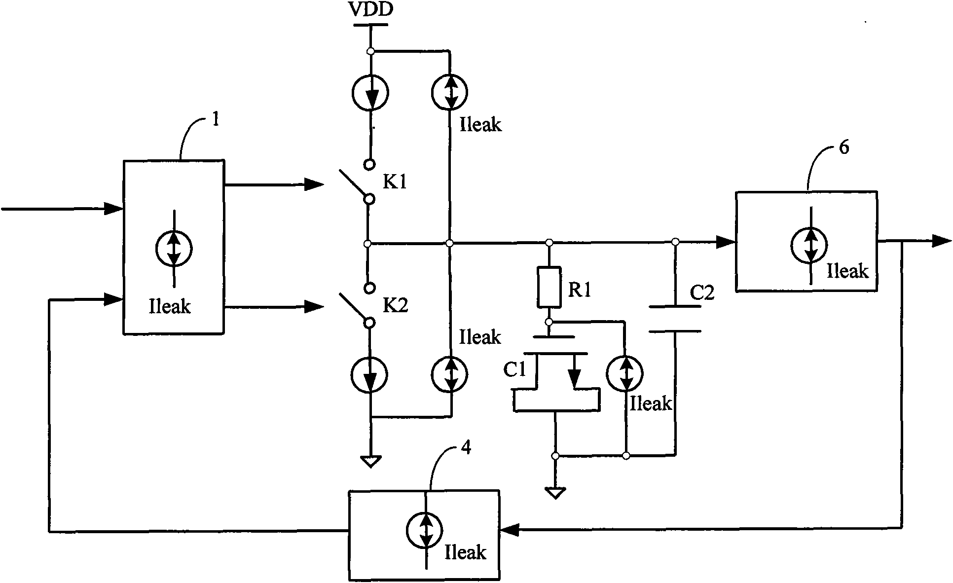
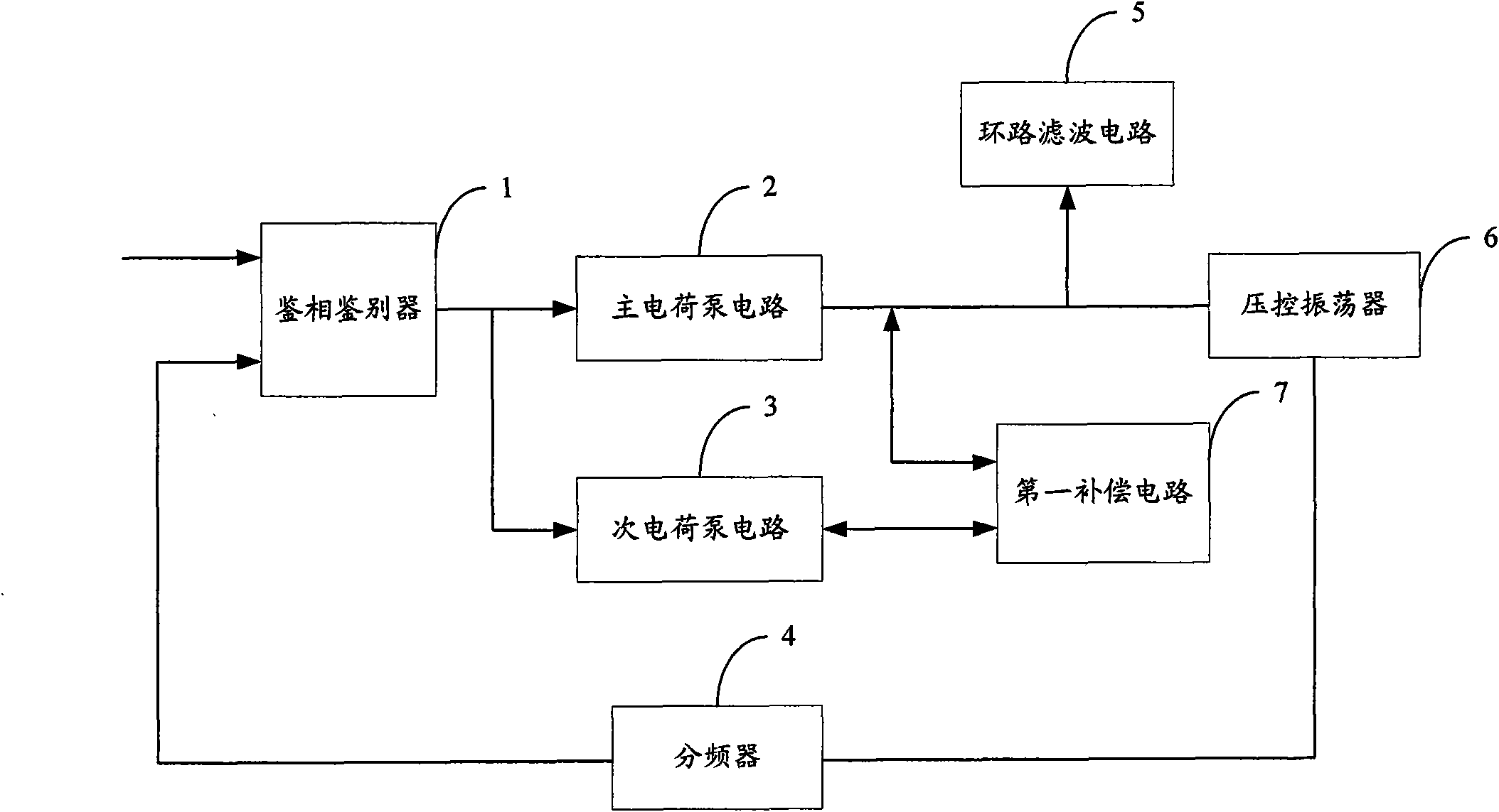
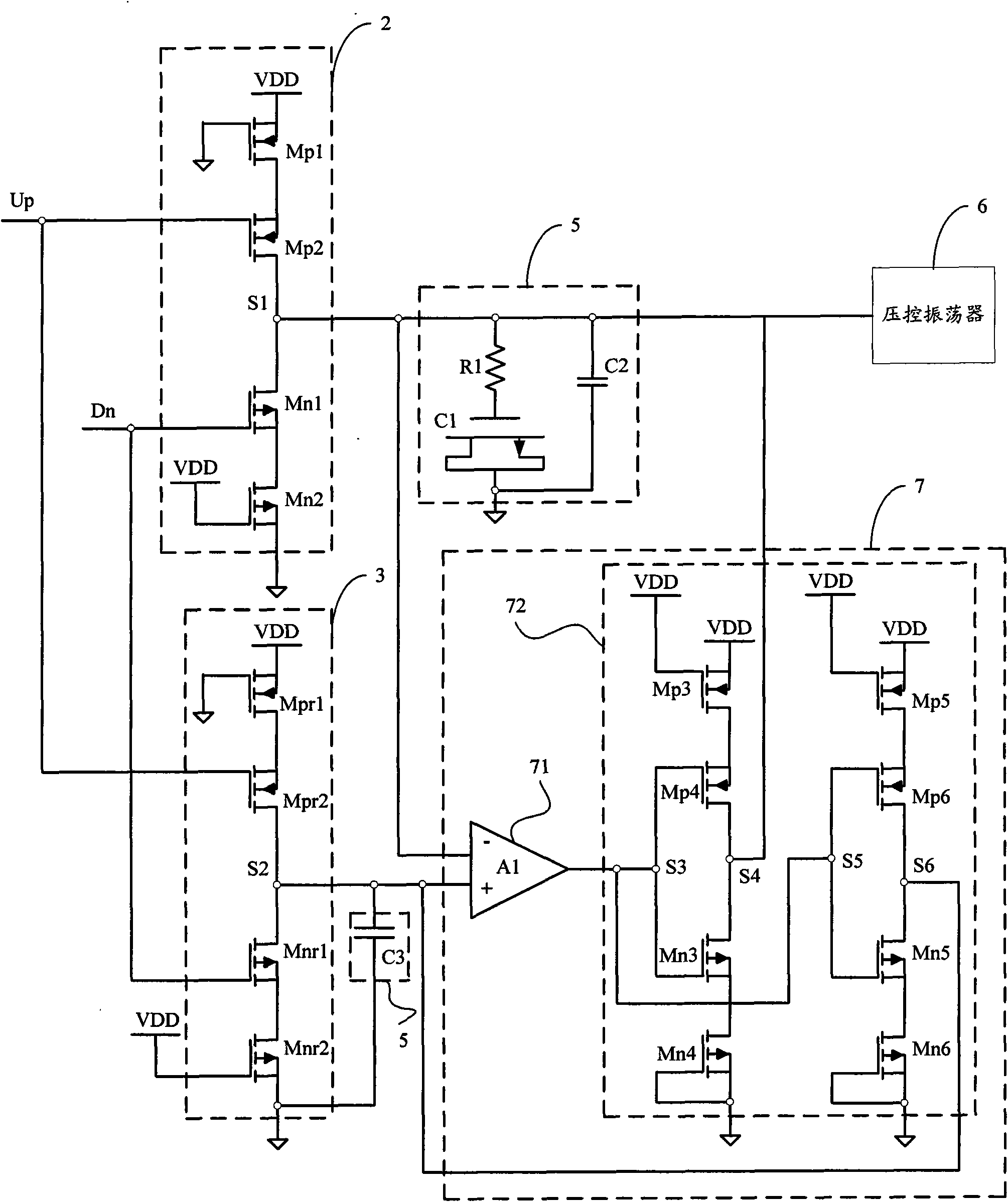
[0047] The phase-locked loop leakage current compensation circuit provided by the embodiment of the present invention uses the first compensation circuit to compensate the leakage current generated in the charge pump circuit, which eliminates the adverse effects caused by the leakage current and ensures the stable performance of the phase-locked loop output frequency .

[0048] The phase-locked loop leakage current compensation circuit provided by the embodiment of the present invention is mainly used in the phase-locked loop circuit to compensate the leakage current generated by the phase-locked loo...


PUM


Abstract

The invention is suitable for the PLL (Phase-Locked Loop) field and provides a PLL leakage current compensation circuit and a PLL circuit. The PLL leakage current compensation circuit comprises a first compensation circuit connected to the output end of a charge pump circuit to compensate a leakage current generated in the charge pump circuit. The PLL leakage current compensation circuit provided by the invention compensates the leakage current generated in the charge pump circuit by adopting the first compensation circuit so as to eliminate adverse influences brought by the leakage current and ensure the stable performance of PLL output frequency, and meanwhile, the PLL leakage current compensation circuit also compensates a leakage current generated in a loop filter circuit by adopting a second compensation circuit to lessen the influence brought by the leakage current in the loop filter circuit, therefore, the performance of the PLL output frequency is ensured and the advantages of chip area reduction and cost saving are achieved..

Description

technical field [0001] The invention belongs to the field of phase-locked loops, in particular to a phase-locked loop leakage current compensation circuit and a phase-locked loop circuit. Background technique [0002] In ultra-deep submicron or more advanced CMOS processes, the leakage current becomes more and more serious as the gate oxide layer becomes thinner and the sub-threshold voltage becomes lower and lower. In 0.13um CMOS process or 90nm CMOS process technology, the design of a phase-locked loop (Phase Locked Loop, PLL) with an operating voltage of about 1V will face the challenge of leakage current constraints; leakage current will increase the additional power consumption of the phase-locked loop and introduce noise. affect its performance indicators. [0003] Typically, in these advanced CMOS processes, the leakage current is mainly divided into three types: (1) tunneling leakage (tunneling leakage) current, which is related to the thickness of the gate oxide la...

Claims


Application Information

Patent Timeline
IPC IPC(8): H03L7/08
Inventor 梁仁光胡胜发
Owner ANYKA (GUANGZHOU) MICROELECTRONICS TECH CO LTD
Features
  • Generate Ideas
  • Intellectual Property
  • Life Sciences
  • Materials
  • Tech Scout
  • Unparalleled Data Quality
  • Higher Quality Content
  • 60% Fewer Hallucinations
Learn More