Coolant pump

A coolant pump and impeller technology, applied in the control of coolant flow, engine cooling, pumps, etc., can solve problems such as prone to failure and complex mechanical structure, and achieve the effect of reducing size and improving preheating behavior

Inactive Publication Date: 2013-05-22
BORGWARNER INC
View PDF1 Cites 0 Cited by
  • Summary
  • Abstract
  • Description
  • Claims
  • Application Information

AI Technical Summary

Problems solved by technology

[0004] However, the design is mechanically complex and prone to failure

Method used


Image

  • Coolant pump
  • Coolant pump
  • Coolant pump

Examples


Embodiment Construction

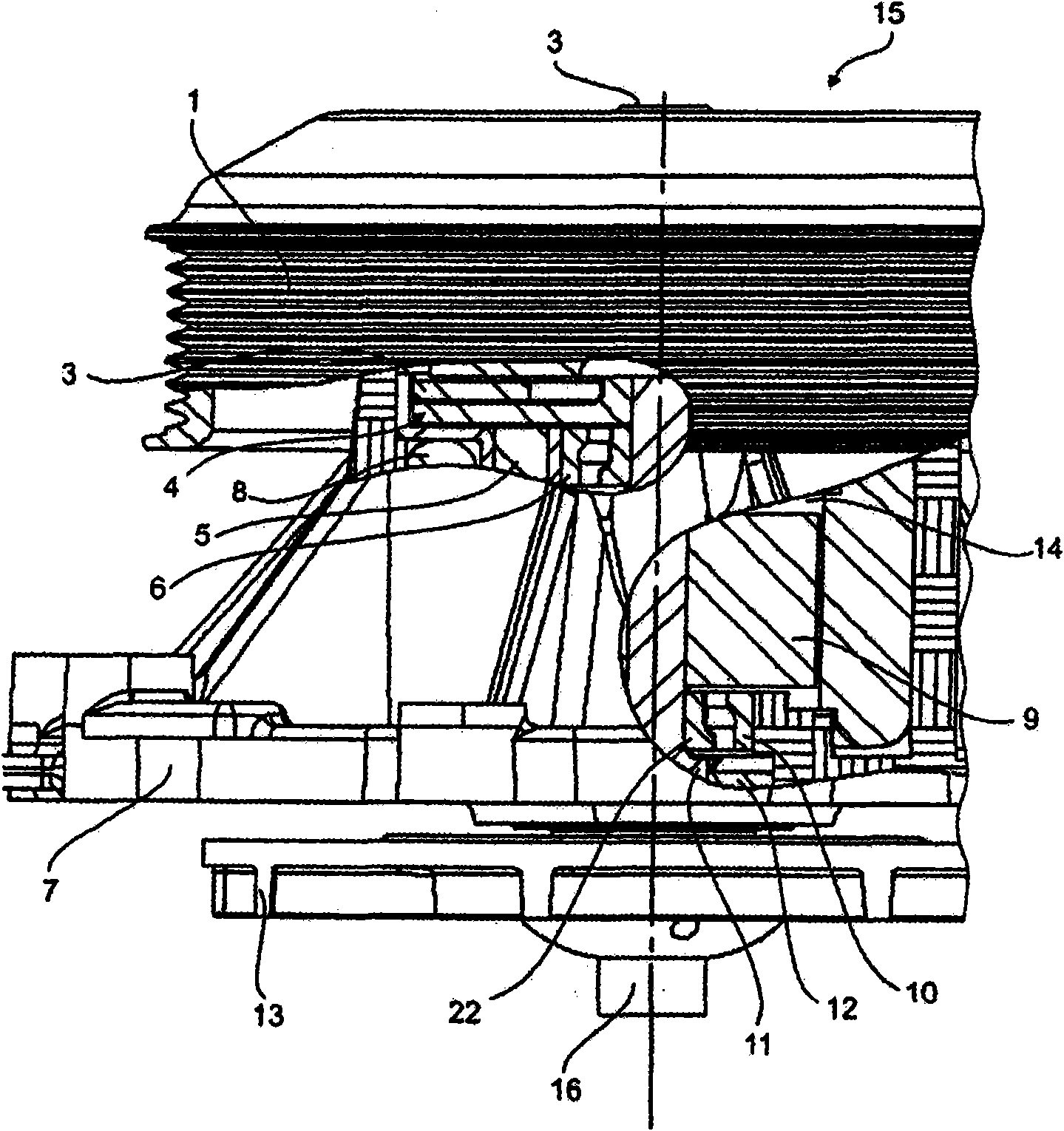
[0032] figure 1 A cross-sectional illustration is shown through an embodiment of a coolant pump 15 according to the invention. The coolant pump 15 has a pump wheel 13 arranged on the pump wheel shaft. The pump shaft is divided into a driving section 3 and a driven section 11 . In the illustrated embodiment, the active section 3 is formed as a flange to which a mechanical drive 1 (in the example in the form of a pulley) is rotationally fixedly connected. In the illustrated embodiment, the arrangement consisting of a flange 3 and a pulley 1 is mounted in a housing 7 via a bearing (not shown).

[0033] The mechanical drive 1 can be connected to the internal combustion engine of a motor vehicle, wherein in the embodiment shown it is possible to use a belt drive, however only the pulley 1 of the belt drive is shown in order to simplify the illustration.

[0034] The driven section 11 of the impeller shaft is mounted in the housing 7 via two bearings 5 ​​and 10 and supports the i...


PUM


Abstract

The invention relates to a coolant pump (15) having a pump wheel (13) which is arranged on a pump wheel shaft (3, 11); and having a drive device (1; 8, 9) for the pump wheel (13), which drive device has a mechanical drive (1) and which drive device has an electric-motor drive (8, 9), wherein the pump wheel shaft is divided into a driving section (3) and a driven section (11), and an openable and closable clutch (4) is arranged between the driving section (3) and the driven section (11).

Description

technical field [0001] The invention relates to a coolant pump according to the preamble of claim 1 . Background technique [0002] A coolant pump of the type mentioned is known from DE 102 14 637 A1. [0003] In order to be able to realize different drive operating states of the vehicle with the coolant pump, which has both an electric motor drive and a mechanical drive, there is provided a planetary drive. [0004] However, said design is complex and prone to failure in terms of its mechanical construction. Contents of the invention [0005] It is therefore the object of the present invention to create a coolant pump of the type defined in the preamble of claim 1 , whose design is simplified with respect to the prior art and whose operation is efficient. and fail-safe. [0006] Said object is achieved by the features of claim 1 . [0007] Since the pump impeller shaft is divided into a driving section and a driven section separate from said driving section, and sinc...

Claims


Application Information

Patent Timeline
Patent Type & Authority Patents(China)
IPC IPC(8): F04D29/58F04B27/08F01P5/10F01P5/12
CPCF01P7/162F04D13/021F01P5/12F04D13/06F04D13/022
Inventor T·布赫兹J·罗斯
Owner BORGWARNER INC
Why Eureka
Try Eureka