
High-precision deep hole processing machine

A processing machine, high-precision technology, used in metal processing machinery parts, metal processing equipment, manufacturing tools and other directions, can solve the problems of inability to achieve precise positioning, inconvenient operation, easy to burn the workpiece, etc., to achieve good protection, drilling Fast hole speed and easy maintenance effect

Inactive Publication Date: 2011-04-13
广东垠星科技发展有限公司
View PDF6 Cites 9 Cited by
  • Summary
  • Abstract
  • Description
  • Claims
  • Application Information

AI Technical Summary

Problems solved by technology

[0002] The existing drilling methods are mostly divided into manual and semi-automatic. The manual drilling method is to hold a gun drill equipped with a drill bit to drill the workpiece to be drilled. However, during manual operation, due to the high-speed operation of the drill gun , It requires a lot of effort to grasp the drill gun. This method cannot achieve accurate positioning during drilling. During the drilling process, because the drill bit rotates at a high speed, the contact with the workpiece will generate high heat, which is easy to burn the workpiece or damage the drill bit.
The semi-automatic drilling method is realized by a drilling machine. The drilling machine can be accurately positioned during use, but its drill bit will also generate high heat. The general solution is to put a basin of water next to the workpiece and pour some after drilling for a while. The water is on the drilling position of the workpiece to cool it down, and the hands must leave the workpiece or the operating rod when pouring water, which is extremely inconvenient to operate, slow in speed and low in efficiency

Method used


Image

  • High-precision deep hole processing machine
  • High-precision deep hole processing machine
  • High-precision deep hole processing machine

Examples


Embodiment Construction

[0017] In order to further understand the features, technical means, and specific objectives and functions achieved by the present invention, the present invention will be further described in detail below in conjunction with the accompanying drawings and specific embodiments.

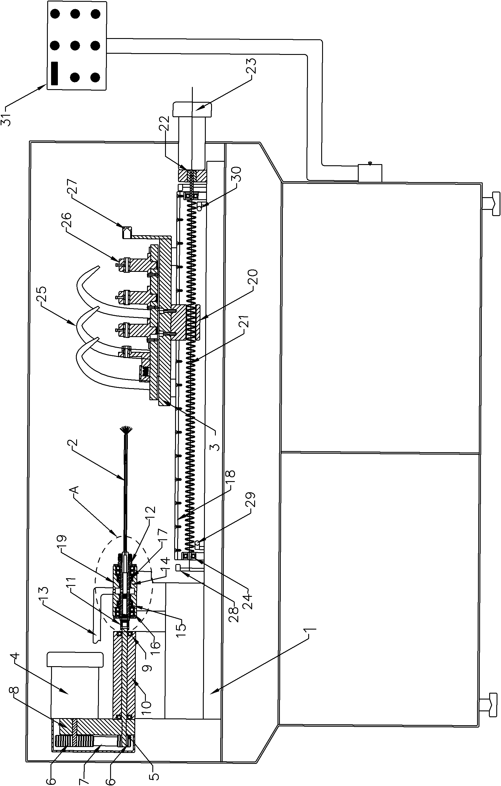
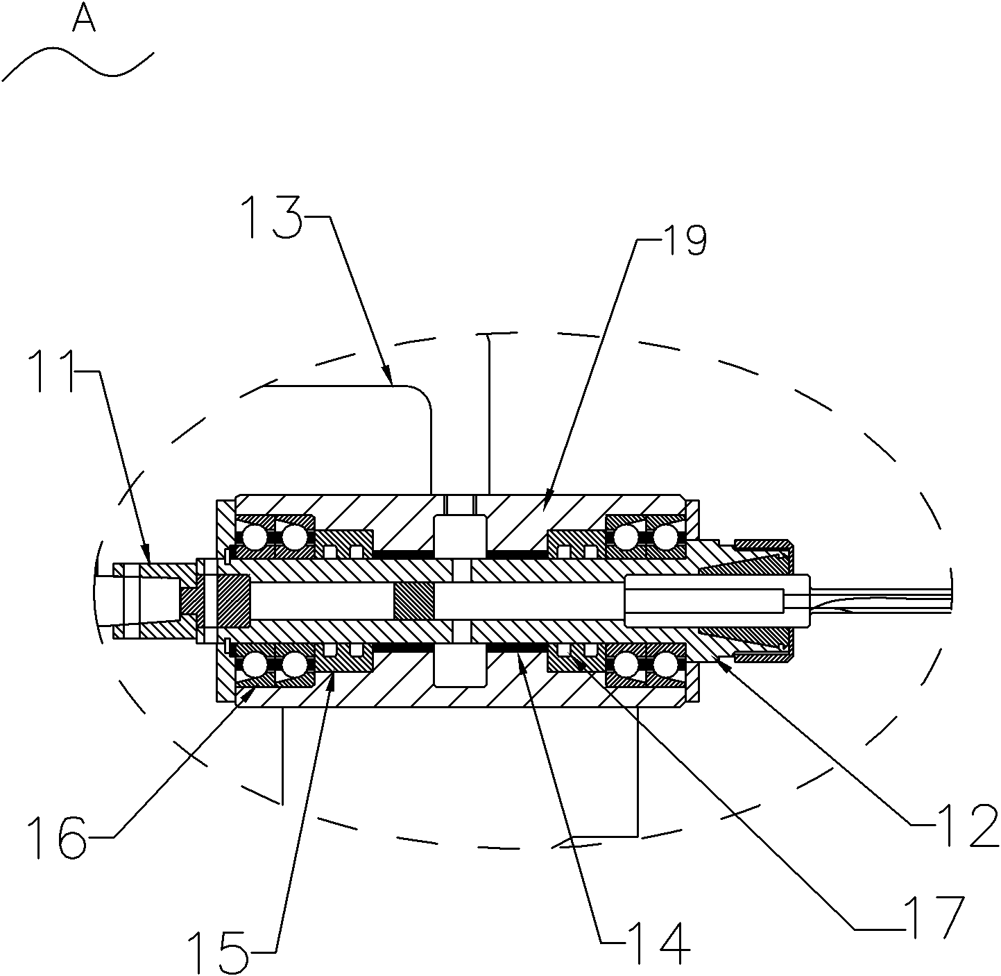
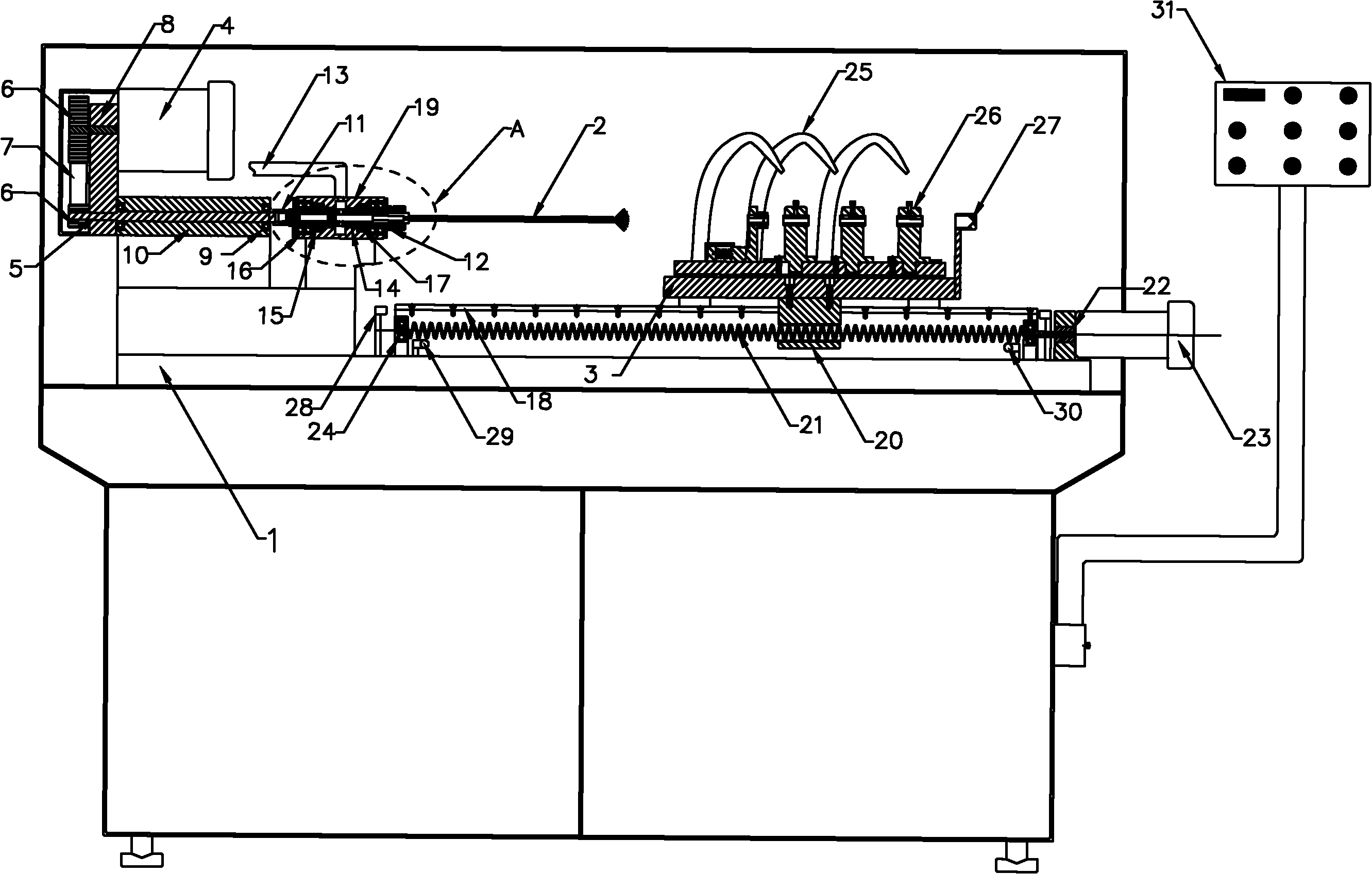
[0018] see figure 1 and figure 2 The high-precision deep hole processing machine of the present invention includes a machine support frame 1, a power mechanism, a gun drill 2 and a workbench 3. The power mechanism is located at the left end of the machine support frame 1, and it is provided with a spindle motor 4 and a transmission shaft 5 . The rotating shaft of the main shaft motor 4 and the transmission shaft 5 are provided with a synchronous wheel 6 , and a synchronous belt 7 is provided between the two synchronous wheels 6 . One end of the main shaft motor 4 is located on one side of the synchronous wheel 6 and a main shaft motor positioning plate 8 is provided. Both ends of the main shaft mot...


PUM


Abstract

The invention discloses a high-precision deep hole processing machine, which comprises a workbench, a power mechanism and a gun drill, wherein the power mechanism is connected with a main shaft, the main shaft is connected with the gun drill, and the main shaft and the gun drill are provided with a shaft cavity and a drill cavity which are mutually communicated respectively; the main shaft is connected with a high-pressure water inlet pipe communicated with the shaft cavity; a metal ring, a sealing ring and a high-speed radial bearing are sleeved on the main shaft positioned on at least one side of the high-pressure water inlet pipe; and the workbench is provided with an outer cooling pipe, and the workbench is erected on a guide rail and is in transmission connection with the power device. The high-precision deep hole processing machine has high drilling speed, high efficiency and high drilling depth, well protects workpieces, and does not need to retract a cutter midway; the drilling depth can reach 100 times diameter of a drill bit; and the processing machine has small floor area and low cost, is easy to maintain, and can be used for automatic batch processing.

Description

technical field [0001] The invention relates to a drilling device, in particular to a high-precision deep hole processing machine. Background technique [0002] The existing drilling methods are mostly divided into manual and semi-automatic. The manual drilling method is to hold a gun drill equipped with a drill bit and drill the workpiece to be drilled. However, during manual operation, due to the high-speed operation of the drill gun , It takes a lot of effort to grasp the drill gun. This method cannot achieve accurate positioning during drilling. During the drilling process, because the drill bit rotates at a high speed, the contact with the workpiece will generate high heat, which is easy to burn the workpiece or damage the drill bit. The semi-automatic drilling method is realized by a drilling machine. The drilling machine can be accurately positioned during use, but its drill bit will also generate high heat. The general solution is to put a basin of water next to the ...

Claims


Application Information

Patent Timeline
Patent Type & Authority Applications(China)
IPC IPC(8): B23B41/02B23B47/00B23B47/18B23Q11/10
Inventor 敖小平
Owner 广东垠星科技发展有限公司
Learn More