Automatic reducing device of seam welder

A rolling welding machine, automatic technology, applied in the direction of auxiliary equipment, welding equipment, auxiliary welding equipment, etc., to achieve the effect of reducing waste, reducing straightening and cutting "processes, and reducing labor intensity

Inactive Publication Date: 2011-04-13
江苏江桥机械制造有限公司
View PDF1 Cites 4 Cited by
  • Summary
  • Abstract
  • Description
  • Claims
  • Application Information

AI Technical Summary

Problems solved by technology

The accumulation of this

Method used


Image

  • Automatic reducing device of seam welder
  • Automatic reducing device of seam welder
  • Automatic reducing device of seam welder

Examples


Embodiment Construction

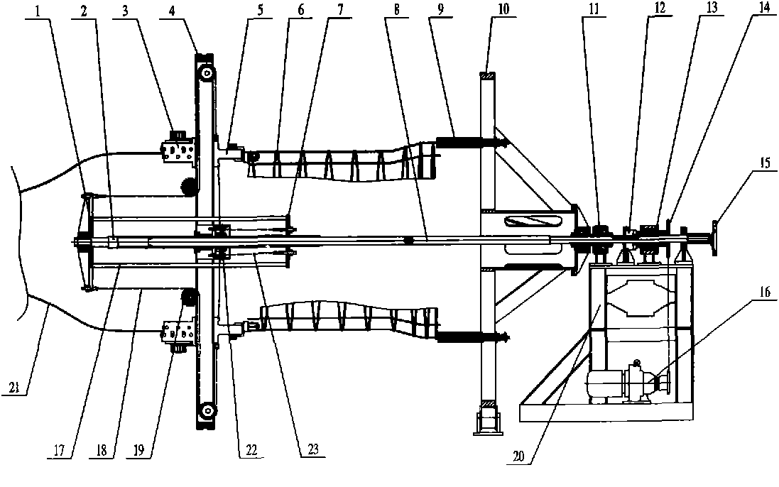
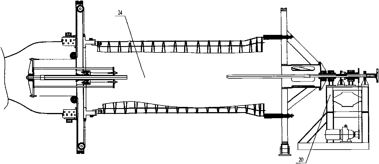
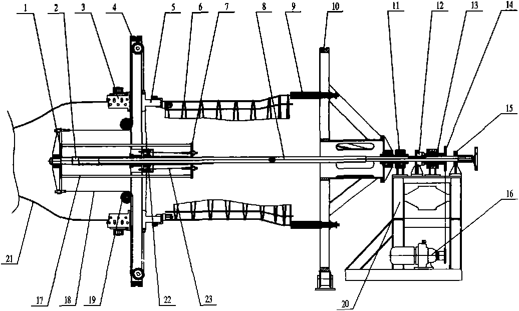
[0015] The present invention as figure 1 , 2 As shown, it includes a frame, a main disc 4, a welding head 5, a tensioning disc 10 coaxial with the main disc 4 and a tendon trolley 20 that drives the tensioning disc 10 to move axially. a radial chute, the welding head 5 is connected to the main disc 4 through the radial chute,

[0016] The automatic diameter-reducing device includes a diameter-reducing cylinder arranged on the main plate 4 to drive the radial movement of the welding head 5; a diameter-reducing cylinder control mechanism arranged on the tendon trolley 20 to control the axial movement of the diameter-reducing cylinder; The center of the main disc 4 is provided with a threaded hole;

[0017] Described reducing cylinder comprises reducing screw mandrel 2, rear disc 1, front disc 7, chain one 18, reversing wheel group one 19, chain two 23, reversing wheel group two 22 and connecting rod 17; The screw rod 2 is connected to the threaded hole in the center of the ma...


PUM


Abstract

The invention provides an automatic reducing device of a seam welder, relating to a reducing mechanism of a cement tube reinforcement cage welding device, which can adapt a continuous vertical rib feeding mode. The automatic reducing device comprises a reducing cylinder and a reducing cylinder control mechanism, wherein the reducing cylinder is arranged on a main disk and used for driving a welding head to move radically, and the reducing cylinder control mechanism is arranged on a tie bar trolley and used for controlling the reducing cylinder to move axially. The main disk is provided with a central hole; the reducing cylinder comprises a reducing screw rod, a rear disk, a front disk, a chain 1, a steering wheel group 1, a chain 2, a steering wheel group 2 and a connection link. The reducing cylinder control mechanism comprises a reducing control rod the cross section of which is a hexagon, a clutch and a driving mechanism; the driving mechanism is fixedly connected to the trolley; and the reducing control rod is connected with the driving mechanism through the clutch. After the reducing control rod of the invention is meshed with the reducing screw rod,, the reducing control rod can drive the reducing screw rod to rotate when rotating; the rotation of the reducing screw rod drives the front disk and the rear disk to move axially; and the axial movement of the front disk and the rear disk can drive the welding head to move radically via the chain 1 and the chain 2, thereby realizing reducing.

Description

technical field [0001] The invention relates to a diameter-changing mechanism of cement pipe-making steel bar skeleton welding equipment. Background technique [0002] At present, domestic drainage pipes are mainly reinforced concrete drainage pipes. The production of reinforced concrete drainage pipes is mainly divided into two steps: steel skeleton production and concrete product molding. Among them, there are two ways to make the steel skeleton: 1. Manual binding; 2. Welding with special equipment. The steel frame is divided into longitudinal bars and ring bars. In the prior art, the processing process of the steel bar frame welding equipment is: first straighten and cut the steel wires to make longitudinal bars, and arrange a certain number of longitudinal bars on the corresponding circumference. All the longitudinal bars rotate around the center, wind the ring bars to the longitudinal bars, and form the required pitch, and perform resistance welding where the longitud...

Claims


Application Information

Patent Timeline
IPC IPC(8): B23K37/00B21F29/00
Inventor 陈学中俞善荣孙祥周佳佳
Owner 江苏江桥机械制造有限公司
Why Eureka
Try Eureka