Hydraulic cylinder plunger installation structure for powder hydraulic press

A powder hydraulic press and installation structure technology, applied in the field of hydraulic press manufacturing, can solve problems such as failure to meet the use requirements of large-tonnage hydraulic presses, broken connecting bolts, and damage to the plunger, so as to improve the service life and equipment work efficiency, and have strong anti-eccentric load capacity. , the effect of improving the service life

Inactive Publication Date: 2011-04-13
TIANJIN TIANDUAN PRESS CO LTD
View PDF4 Cites 8 Cited by
  • Summary
  • Abstract
  • Description
  • Claims
  • Application Information

AI Technical Summary

Problems solved by technology

[0002] With the continuous advancement of science and technology in our country, the demand for heavy machinery is also increasing, and the application of large-tonnage hydraulic presses is also increasing, especially for free forging hydraulic presses. The tonnage has risen from a few thousand tons to tens of thousands of tons. The plunger structure can no longer meet the requirements of large-tonnage hydraulic presses
The traditional hydraulic cylinder plunger installation structure is: simply install a plunger in the cylinder body, and the output end of the plunger is connected to an external connector. This structure is suitable for use in small-tonnage hydraulic presses; The plunger of this structure bears a large partial load force, and if it is used for a long time, not only the plunger will be damaged, but also the wear of other related parts will be accelerated, and accidents such as broken connecting bolts may even occur.

Method used


Image

  • Hydraulic cylinder plunger installation structure for powder hydraulic press
  • Hydraulic cylinder plunger installation structure for powder hydraulic press

Examples


Embodiment Construction

[0012] In order to further understand the invention content, characteristics and effects of the present invention, the following examples are given, and detailed descriptions are as follows in conjunction with the accompanying drawings:

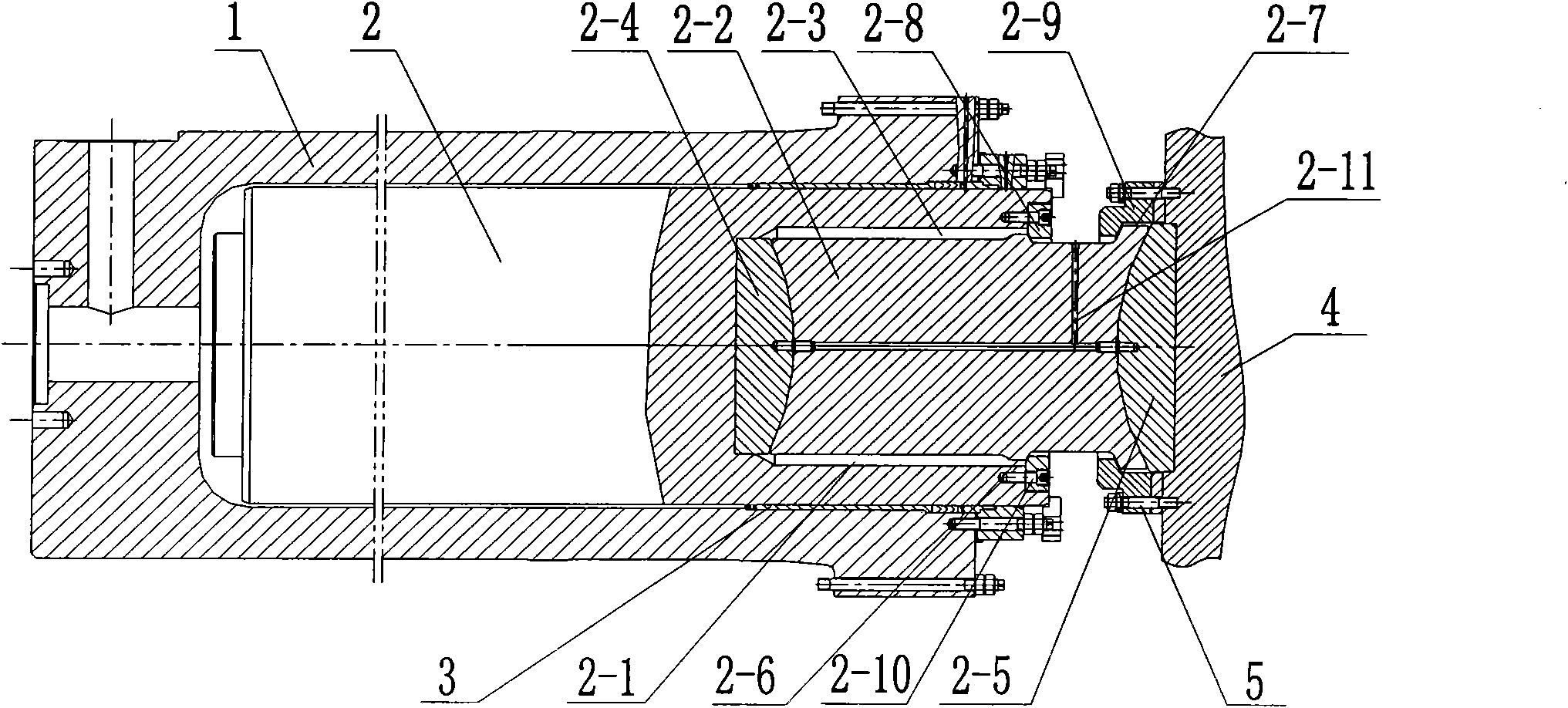
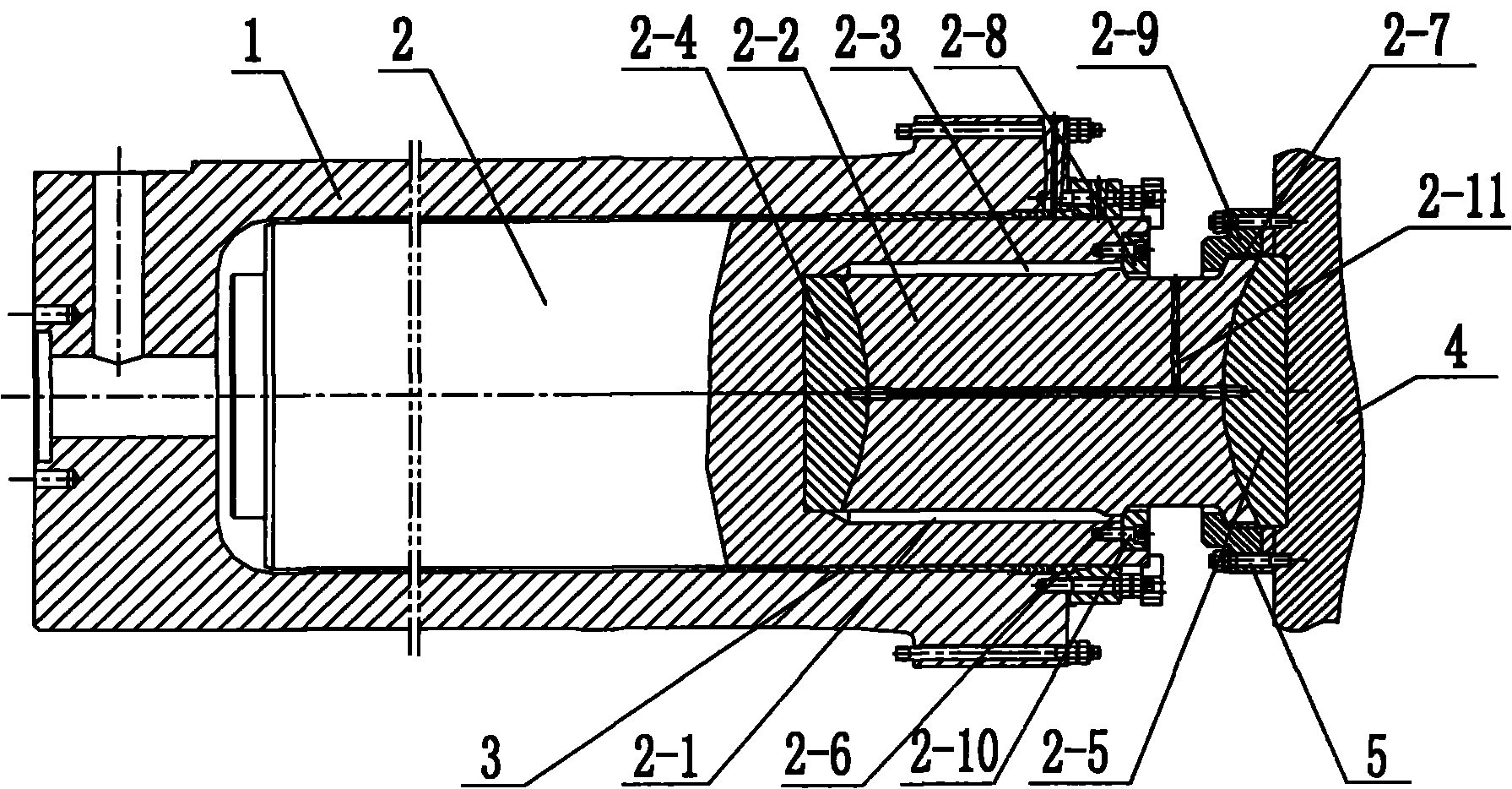
[0013] see figure 1 , a hydraulic cylinder plunger installation structure for powder hydraulic presses, including a cylinder body 1, a plunger 2 installed in the cylinder body 1, and a guide sleeve 3 between the plunger 2 and the cylinder body 1, and the plunger 2 A central blind hole 2-1 is provided at the outer connection end of the central blind hole 2-1, and a spherical column 2-2 is installed in the central blind hole 2-1, and an eccentric load gap 2-3 is left between the spherical column 2-2 and the central blind hole 2-1. A spherical pad 2-4 is provided between the spherical column 2-2 and the bottom of the central blind hole 2-1; a spherical pad 2-5 is provided between the other end of the spherical column 2-2 and the outer connector ...


PUM


Abstract

The invention relates to a hydraulic cylinder plunger installation structure for a powder hydraulic press, comprising a cylinder body, a plunger and a guide sleeve. The hydraulic cylinder plunger installation structure is characterized in that a center blind hole is arranged at the outer connecting end of the plunger; a spherical column is arranged in the center blind hole; an unbalance loading gap is reserved between the spherical column and the center blind hole; a spherical pad is arranged between the spherical column and the center blind hole; a spherical pad is arranged between the other end of the spherical column and the outer connecting piece; two annular lug bosses are arranged on the spherical column; and two split flanges are symmetrically arranged between the two annular lug bosses, wherein one flange is connected with the plunger, and the other flange is clamped on the annular lug boss positioned outside and connected with the outer connecting piece. When the hydraulic press bears unbalance load, the spherical column realizes the unbalance load compensation along the spherical trace in a certain angle range and the wear of the plunger and other relevant components is reduced to the minimum when large unbalance force is applied, thereby prolonging the service life of the components and improving the work efficiency of the equipment.

Description

technical field [0001] The invention belongs to the technical field of hydraulic press manufacturing, and in particular relates to a hydraulic cylinder plunger installation structure for powder hydraulic presses. Background technique [0002] With the continuous advancement of science and technology in our country, the demand for heavy machinery is also increasing, and the application of large-tonnage hydraulic presses is also increasing, especially for free forging hydraulic presses. The tonnage has risen from a few thousand tons to tens of thousands of tons. The plunger structure can no longer meet the requirements of large-tonnage hydraulic presses. The traditional hydraulic cylinder plunger installation structure is: simply install a plunger in the cylinder body, and the output end of the plunger is connected to an external connector. This structure is suitable for use in small-tonnage hydraulic presses; This kind of structural plunger bears a large partial load force, ...

Claims


Application Information

Patent Timeline
Patent Type & Authority Applications(China)
IPC IPC(8): B30B1/32
CPCB30B15/065
Inventor 曹春娥
Owner TIANJIN TIANDUAN PRESS CO LTD
Why Eureka
Try Eureka