
Pneumatic powder conveying gas material separation and decompression device and process

A technology of pneumatic conveying and decompression device, which is used in conveying bulk materials, conveyors, transportation and packaging, etc. It can solve the problem of increasing the impact wear of the inner wall of the launder, the flying leakage of powder raw materials, and reducing the use of launders. life and other problems, to solve the loss of raw materials, avoid flying leakage or leakage, and improve the service life.

Active Publication Date: 2011-04-13
产学研共同体(山东)科技成果转化有限公司
View PDF6 Cites 8 Cited by
  • Summary
  • Abstract
  • Description
  • Claims
  • Application Information

AI Technical Summary

Problems solved by technology

[0002] At present, the powder conveying technology widely used in the powder industry is full-line high-pressure conveying. Since the air conveying pressure is mostly above 100KP, a large amount of powder raw materials will often fly when the air is conveyed through the trough and the filling bin. Type leakage, resulting in the waste of some resources and environmental pollution, and increase the impact of wear on the inner wall of the convection trough, reducing the service life of the trough

Method used


Image

  • Pneumatic powder conveying gas material separation and decompression device and process
  • Pneumatic powder conveying gas material separation and decompression device and process
  • Pneumatic powder conveying gas material separation and decompression device and process

Examples


Embodiment 1

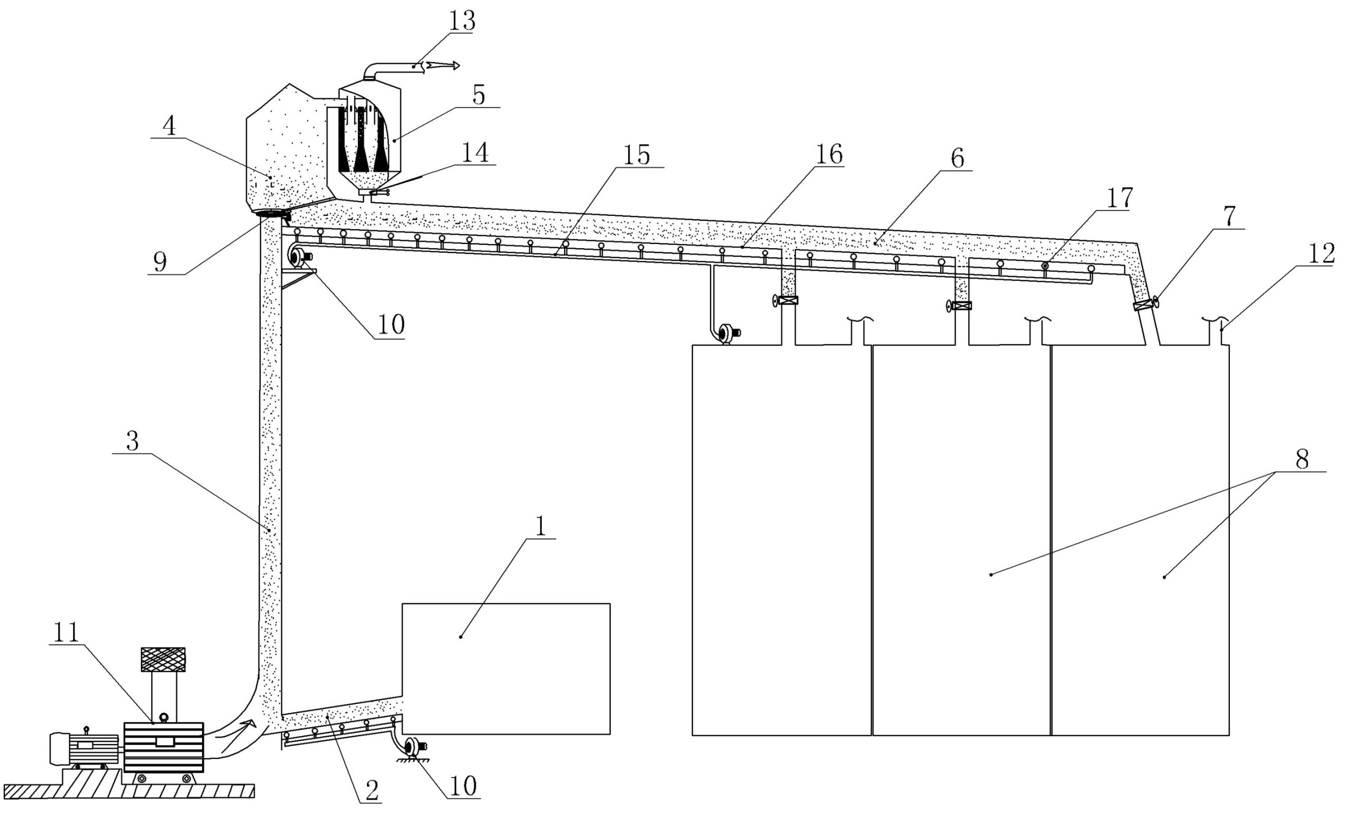
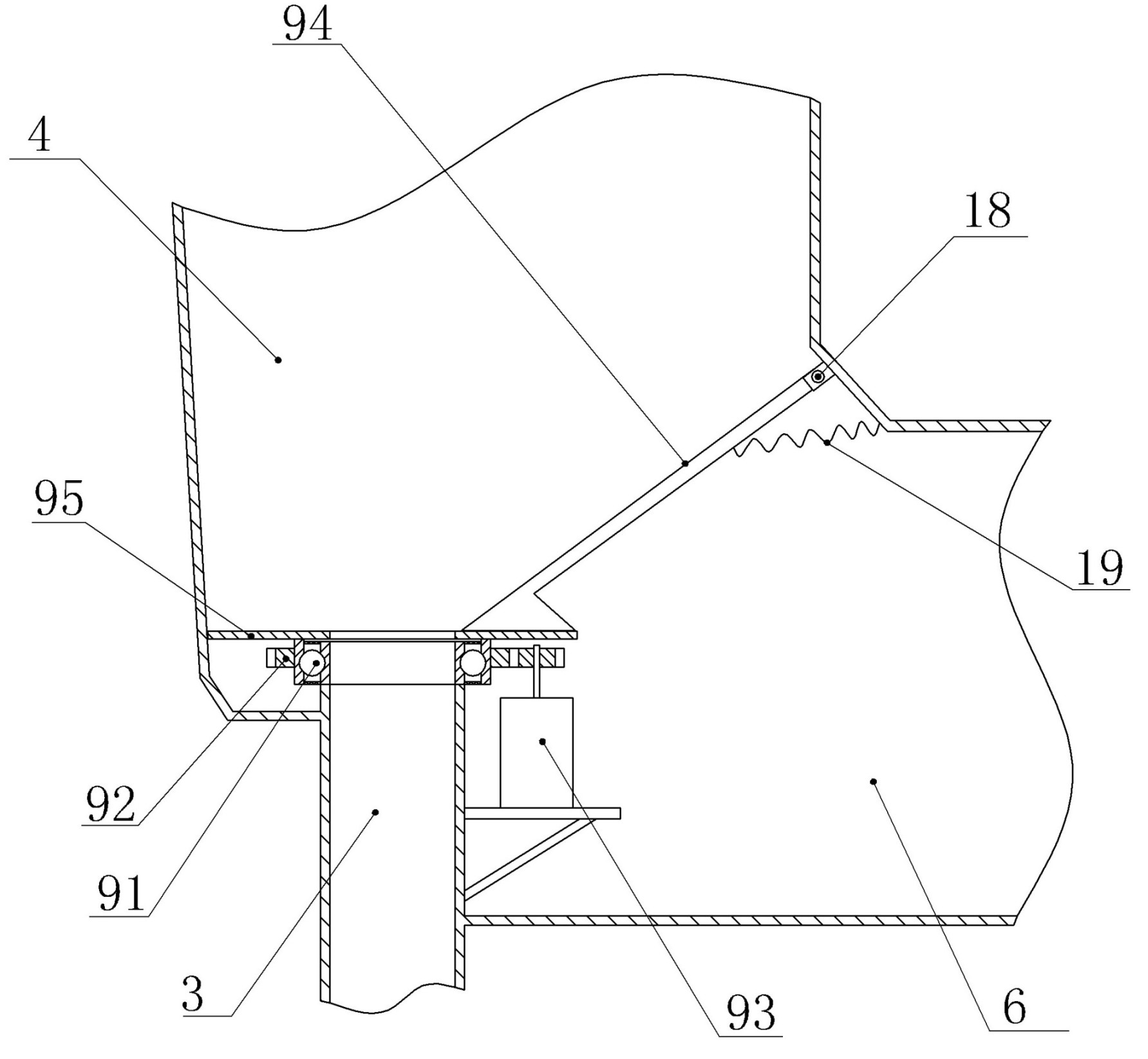
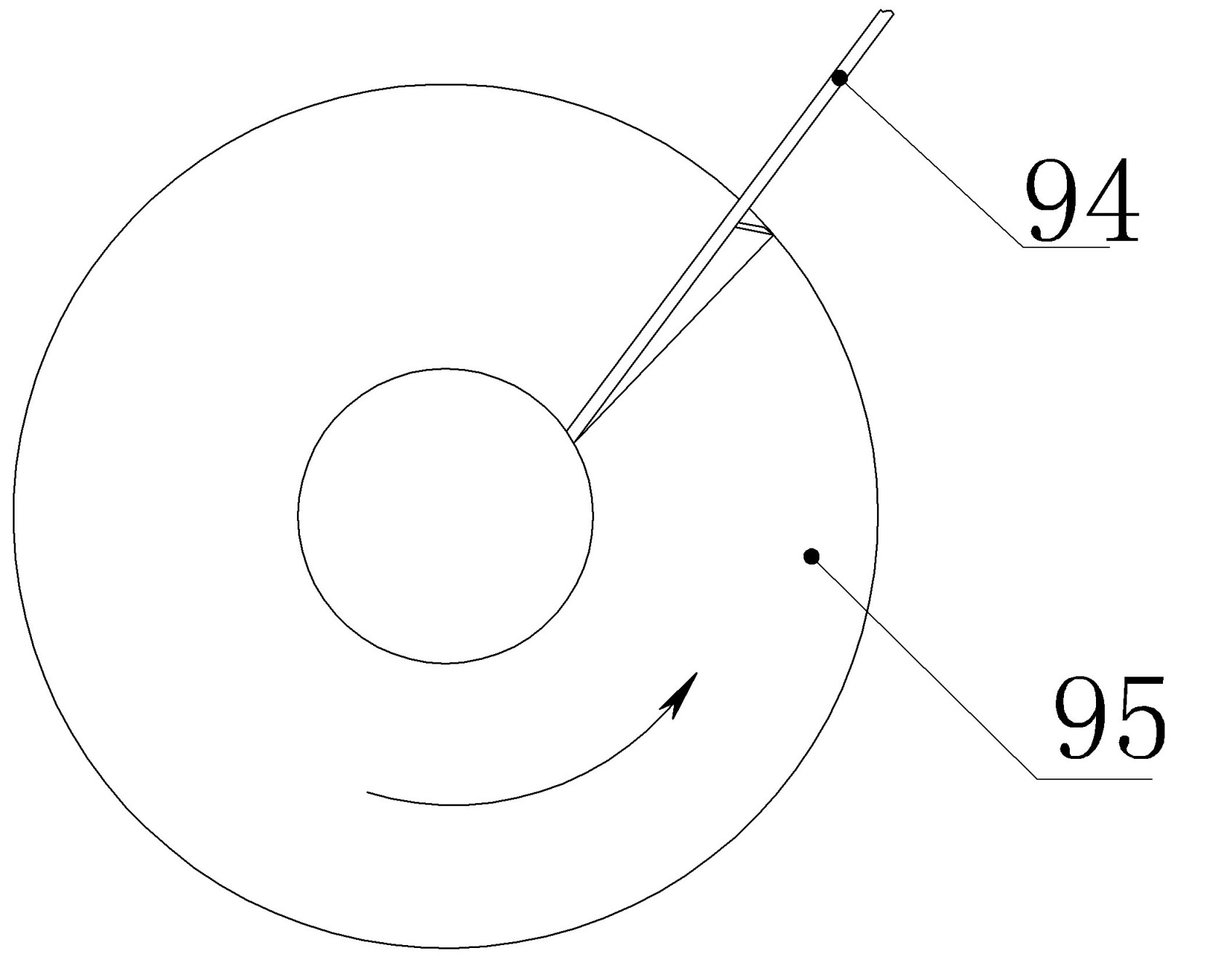
[0032] Embodiment one: see figure 1 — Figure 8 , label 1 is the powder production source, 2 is the feeding chute, 3 is the pneumatic lifting pipeline, 4 is the dust-reducing splitter, 5 is the axial-flow high-efficiency cyclone dust collector, 6 is the tank chute, and 7 is the tank Branch pipe and tank valve, 8 is the powder storage bin, 9 is the feeder, 10 is the axial flow fan, 11 is the Roots blower, 12 is the dust removal exhaust pipe, 13 is the main exhaust pipe (connected with the dust removal and purification system ), 14 is a gravity blanking valve, 15 is a feeding air pipe of a tank launder, 16 is an air material cloth interlayer, 17 is a feeding air valve, 18 is a bearing pin, and 19 is a return spring. 501a and 501b are the upper cylindrical section and the lower conical section of the shell respectively, 502 is the exhaust pipe, 503 is the sealing plate fixedly supported, 504 is the arc guide vane, 505 is the air inlet, 506 is the discharge port , 507 is the tot...

Embodiment 2

[0040] Embodiment two: see figure 1 , a powder pneumatic conveying gas material separation and decompression process, comprising the following steps:

[0041] (1) The powder production source transports the powder raw materials along the feeding trough to the confluence of the lower mouth of the pneumatic lifting pipeline;

[0042] (2) Use the fan to output high-pressure airflow above 100KP to gasify the powder raw material in the lower part of the air lift pipe and then lift it up to the top of the air lift pipe;

[0043] (3) Perform gravity dust reduction and diversion treatment on the high-pressure and high-speed gas material lifted in step (2), forming the buffered mainstream gas and most of the materials that sink due to gravity, and most of the sinking materials fall into the dial The material tray is dialed into the tank chute, and poured into each silo by pneumatic push at the bottom of the chute;

[0044] (4) The mainstream gas formed in step (3) is subjected to cyc...


PUM


Abstract

The invention relates to a pneumatic powder conveying gas material separation and decompression device and a pneumatic powder conveying gas material separation and decompression process. The device comprises a powder production source, a baiting conveying launder, a Roots blower and a silo launder; and the air outlet of the upper end of a pneumatic lifting pipeline is connected with a bottom kick-out device bearing inner sleeve of a dust settling diverter, the lower end of the dust settling diverter is communicated with the silo launder, the upper part of the dust settling diverter is communicated with the main air inlet of the upper end of an axial flow type efficient cyclone dust collector, the main discharge hole of the lower end of the efficient cyclone dust collector is communicated with the silo launder, and the main air outlet of the upper end of the efficient cyclone dust collector is communicated with a dust removal purification system. By using gas material separation technology, the original all-line high-pressure conveying is divided into two zones of high pressure and low pressure so that the high-pressure lifting section has enough energy, the launder micro-angle conveying and the silo form a low-pressure pneumatic conveying zone and the shunt gas realizes purified micro powder reclamation; therefore, the low-pressure conveying purpose of the silo is radically fulfilled.

Description

Technical field: [0001] The invention relates to the technical field of gas-material separation, dust removal and purification, in particular to a gas-material separation and decompression device and process for pneumatic conveying of powder. Background technique: [0002] At present, the powder conveying technology widely used in the powder industry is full-line high-pressure conveying. Since the air conveying pressure is mostly above 100KP, a large amount of powder raw materials will often fly when the air material passes through the launder and filling bin during the conveying process. Type leakage, resulting in the waste of some resources and environmental pollution, and increase the impact of wear on the inner wall of the convection trough, reducing the service life of the trough. This phenomenon has long been a major problem in the pneumatic conveying process. Invention content: [0003] In order to overcome the deficiencies and shortcomings of the existing technolo...

Claims


Application Information

Patent Timeline
Patent Type & Authority Applications(China)
IPC IPC(8): B65G53/60
Inventor 吴传仪吴忠良李冰刘涛
Owner 产学研共同体(山东)科技成果转化有限公司
Learn More