

Hydraulic type portal frame
A gantry, hydraulic technology, applied in the direction of lifting frame, hoisting device, hoisting equipment braking device, etc., can solve the problems of inconvenient transportation and installation, high manufacturing cost, time-consuming use, etc., and achieve small impact and wear resistance Good, easy to repair and replace parts
Inactive Publication Date: 2011-04-13
SHAOXING UNIVERSITY +2
View PDF4 Cites 1 Cited by
- Summary
- Abstract
- Description
- Claims
- Application Information
AI Technical Summary
Problems solved by technology
At present, the common hydraulic systems or hydraulic machines mostly adopt the structure of three beams and four columns or two beams and four columns. The hydraulic presses or hydraulic systems of this structure mainly have the following disadvantages: 1. The structure is complicated. Due to the use of three beams and four columns or two beams and four columns The structure will bring inconvenience to transportation and installation; 2. The manufacturing cost is high, and the use is time-consuming and laborious; 3. When working, the noise is loud and the environmental protection is poor
Method used
View moreImage
Smart ImageViewing Examples

Examples
Embodiment 1
Login to View More PUM
 Abstract
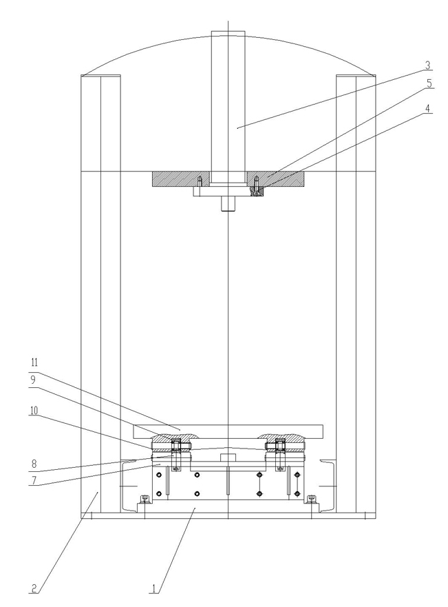
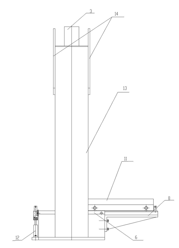
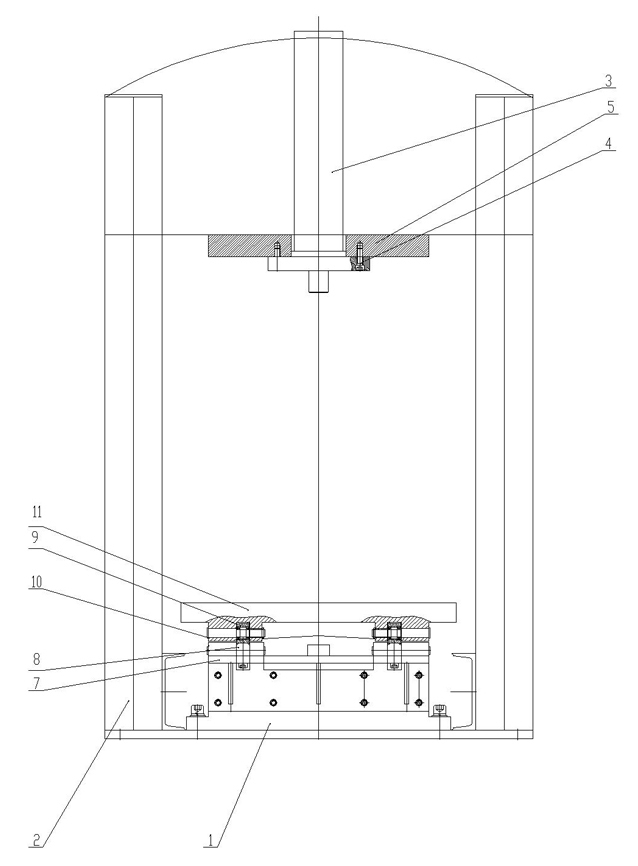
The invention discloses a hydraulic type portal frame which comprises a base and a rack installed on the base, wherein a difunctional hydraulic cylinder is installed on the top of the rack, the bottom of the difunctional hydraulic cylinder is provided with a work platform through a screw, the base is provided with a bracket, a support plate is installed on one side of the bracket, and a guide rail is installed on the support plate, extends into the bracket, and is fixedly connected with the bracket; a guide wheel is movably installed on the guide rail, the guide wheel is provided with a guide wheel shaft, and the guide wheel shaft is installed in a chute on the lower end of a work sliding table; and a single acting hydraulic cylinder is installed on of the base at the other side of the work sliding table. The invention provides a hydraulic machine which has the advantages of reasonable structure and lower production cost, and is lighter and more convenient.
Description
technical field [0001] The invention relates to a hydraulic gantry frame. Background technique [0002] The gantry frame is mainly composed of five parts: beams, columns, chassis, guide beams and fulcrums, which are used as supports for lifting equipment, such as gantry crane supports. The two pillars are like Panlong pillars, and the image is called Longmen frame. Hydraulic transmission began to be used at the end of the eighteenth century, but it was widely used in industry for a relatively short time. The hydraulic system has been greatly developed in recent years because of its small size, light weight, infinitely variable speed, stable movement, and long working life. At present, the common hydraulic systems or hydraulic machines mostly adopt the structure of three beams and four columns or two beams and four columns. The hydraulic presses or hydraulic systems of this structure mainly have the following disadvantages: 1. The structure is complicated. Due to the use of...
Claims
Login to View More Application Information
Patent Timeline
 Patent Type & AuthorityApplications(China)
IPC IPC(8): B66C5/02B66F7/00
Inventor王文奎俞学人
OwnerSHAOXING UNIVERSITY