Soil body in situ test device and test method applying same

A technology of in-situ testing and rock and soil mass, which is applied in the field of foundation soil survey, construction, infrastructure engineering, etc. Test problems such as complex stress conditions to achieve intuitive measurement results

Active Publication Date: 2011-04-13
广东永基建筑基础股份有限公司
View PDF4 Cites 27 Cited by
  • Summary
  • Abstract
  • Description
  • Claims
  • Application Information

AI Technical Summary

Problems solved by technology

[0004] However, the stress conditions of in-situ tests are complex, and it is generally difficult to determine a certain parameter of rock and soil intuitively. Therefore, some simplified assumptions will have to be adopted when selecting calculation models and determining boundary conditions, and the resulting errors may also be The obtained geotechnical parameters cannot ideally represent the properties of the actual soil
In-situ penetration testing also has a big disadvantage: it cannot directly observe the underground soil, and engineers must classify and evaluate the soil based on electrical soil parameters and experience
This penetrating method is often used to estimate the bearing capacity of the foundation. The measured cone tip resistance and side wall friction can more intuitively reflect the degree of softness and hardness of the soil, but the measured parameters are too few to obtain a more accurate understanding of the soil layer. other properties of
In addition, although the penetration of the probe is a good simulation of the force on the pile, due to the differences between the probe and the pile in terms of size, material, pressing speed, etc., the mechanical index of the penetrating test and the resistance value of the pile are not exactly the same, and cannot be directly used to estimate the pile sinking resistance of piles

Method used


Image

  • Soil body in situ test device and test method applying same
  • Soil body in situ test device and test method applying same
  • Soil body in situ test device and test method applying same

Examples


Embodiment Construction

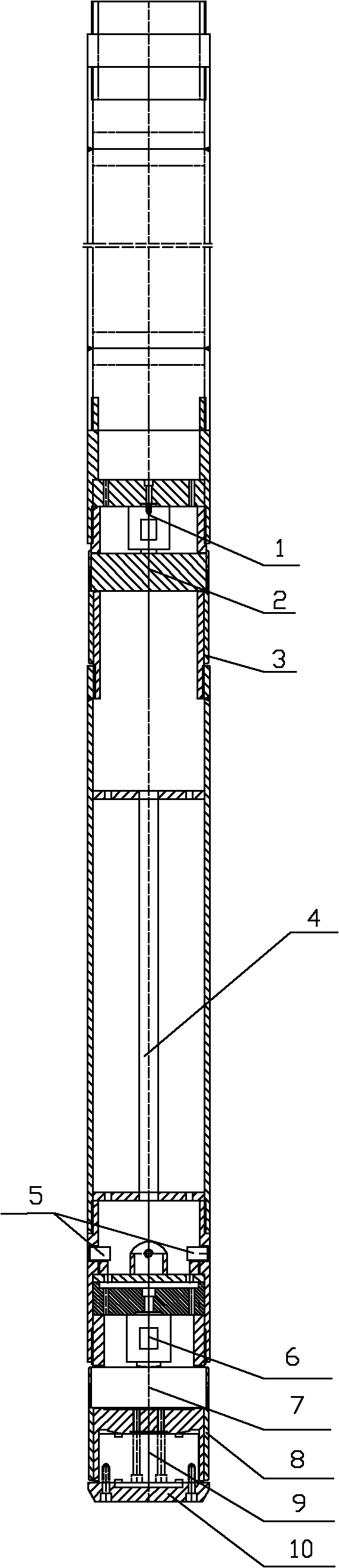
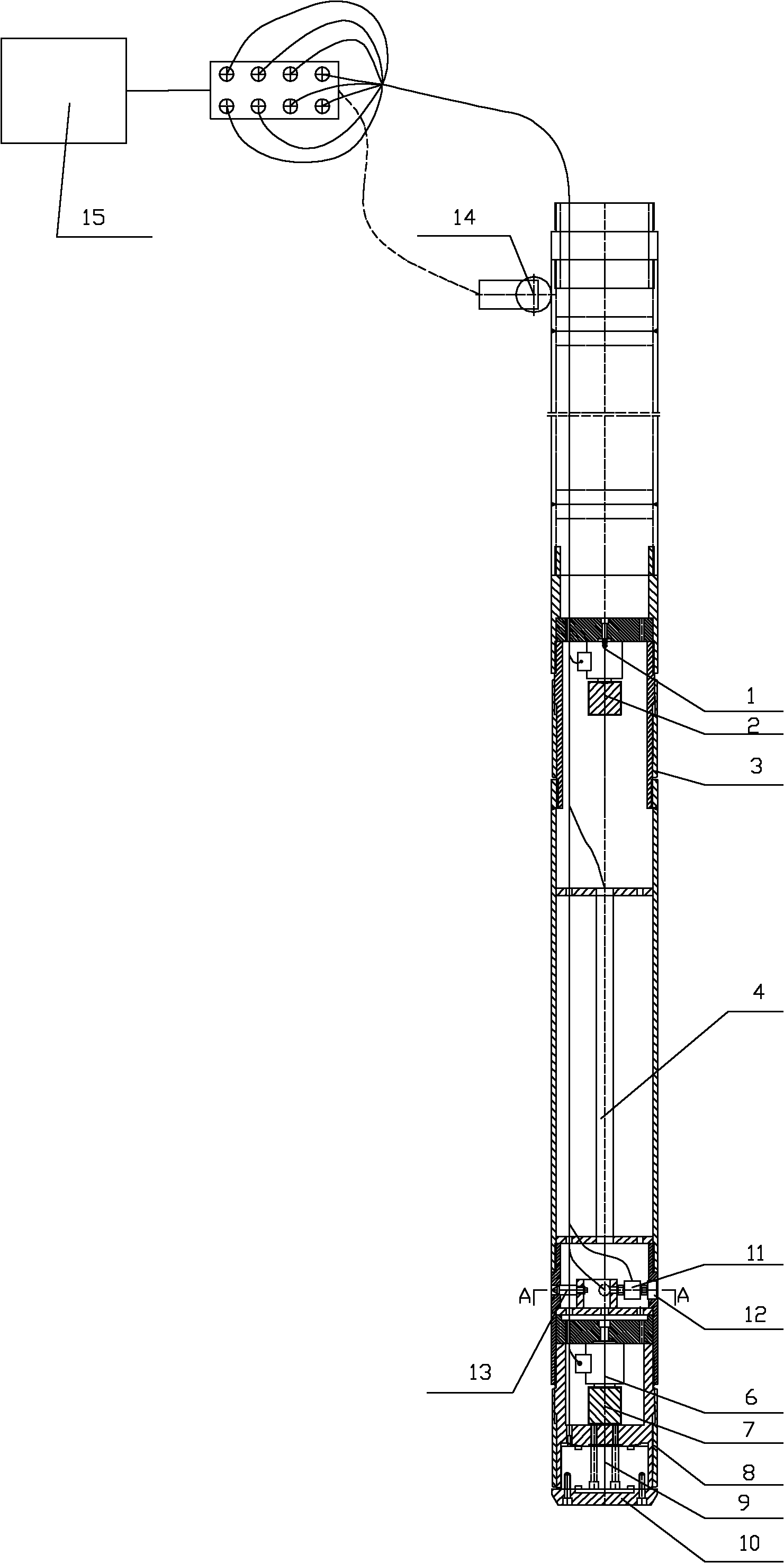
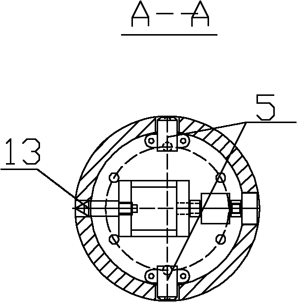
[0031] The specific implementation manner of the present invention will be described in detail below in conjunction with the accompanying drawings. Figure 1-Figure 3 One embodiment of the in situ testing apparatus for rock and soil mass of the present invention is shown.

[0032] Such as Figure 1-Figure 3 The equipment of this embodiment shown includes a steel pipe with the same shape as the pipe pile. The cross-sectional size and shape of the steel pipe are the same as those of the pipe pile, and the cross-section can be circular or square. A pile tip plate 10 and a first pressure sensor 9 for sensing the pressure on the pile tip plate 10 are arranged at one end of the steel pipe. The pile tip plate 10 is perpendicular to the side wall of the steel pipe. When the pile tip plate is stressed, it presses the first pressure sensor 9 , and the first pressure sensor 9 sends out an electric signal when it is stressed, and the electric signal is received by the data collector 15 ....


PUM


Abstract

The invention relates to a soil body in situ test device, comprising a steel tube with the same shape of tubular pile as well as a data collector; wherein one end part of the steel tube is provided with a pile point plate and a first pressure sensor used for sensing pressure born by the pile point plate, the pile point plate is vertical to the side wall of the steel tube; more than one side wall friction drum is arranged along the radial direction of the steel tube, and each side wall friction drum is provided with a second pressure sensor used for sensing the friction force born by the side wall friction drum; the side wall friction drum forms one part of the side wall of the steel tube; one part of the side wall of the steel tube is set to be a movable lateral compression plate and is provided with a third pressure sensor used for sensing the pressure born by the lateral compression plate; the side wall of the steel tube is internally provided with a pore pressure gauge and a camera; and electrical signals sent by the first, second and third pressure sensors and the pore pressure gauge are all collected by the data collector. The device can test and read multiple data, thus being convenient for accurately analyzing soil body properties. The invention also discloses an in situ test method applying the device.

Description

technical field [0001] The invention belongs to the technical field of civil engineering and geotechnical engineering, and relates to in-situ testing equipment for rock and soil bodies and an in-situ testing method using the equipment. Background technique [0002] At present, how to accurately judge soil properties is generally through exploration and testing methods. There are two main methods: (1) field exploration, including pit exploration, drilling, geophysical exploration, etc.; (2) in-situ testing, including static Force penetration test, standard penetration test, field cross plate shear test, lateral pressure test, etc. [0003] Among them, in-situ testing is not only an important part of geotechnical engineering investigation, but also the main means of quality inspection of geotechnical engineering construction. The in-situ test method is used to measure the engineering properties of the rock and soil mass, and the engineering properties of the rock and soil mas...

Claims


Application Information

Patent Timeline
Patent Type & Authority Applications(China)
IPC IPC(8): E02D1/02
Inventor 黎志中
Owner 广东永基建筑基础股份有限公司
Why Eureka
Try Eureka