Split hydraulic clamp

A hydraulic pliers, split technology, used in hand-held tools, manufacturing tools, electrical components, etc., can solve the problems of poor pressure bearing effect, waste of materials, looseness and deformation, etc., to achieve center alignment, convenient transportation, and small deformation. Effect

Inactive Publication Date: 2012-12-05
吴书占
View PDF0 Cites 0 Cited by
  • Summary
  • Abstract
  • Description
  • Claims
  • Application Information

AI Technical Summary

Problems solved by technology

[0004] 2. It uses the upper mold bracket A3 and the lower mold bracket A4 in structure, the upper mold bracket A3 and the clamp upper cover A2 are fixedly connected together by screws, the lower mold bracket A4 and the piston A5 are fixed together, This is a waste of material, and the pressure bearing effect is poor
[0005] 3. The matching positioning device between the upper cover A2 of the clamp and the body A1 of the clamp and the positioning device between the upper cover of the clamp and the mold are easy to cause loosening and deformation

Method used


Image

  • Split hydraulic clamp
  • Split hydraulic clamp
  • Split hydraulic clamp

Examples


Embodiment Construction

[0034] The following descriptions are only preferred embodiments of the present invention, and therefore do not limit the protection scope of the present invention.

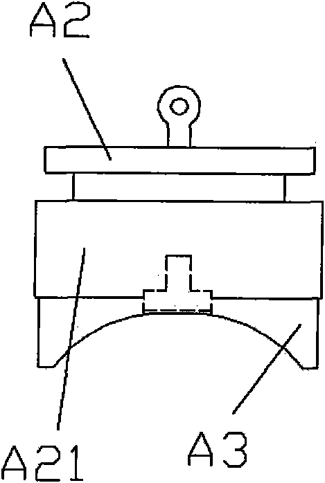
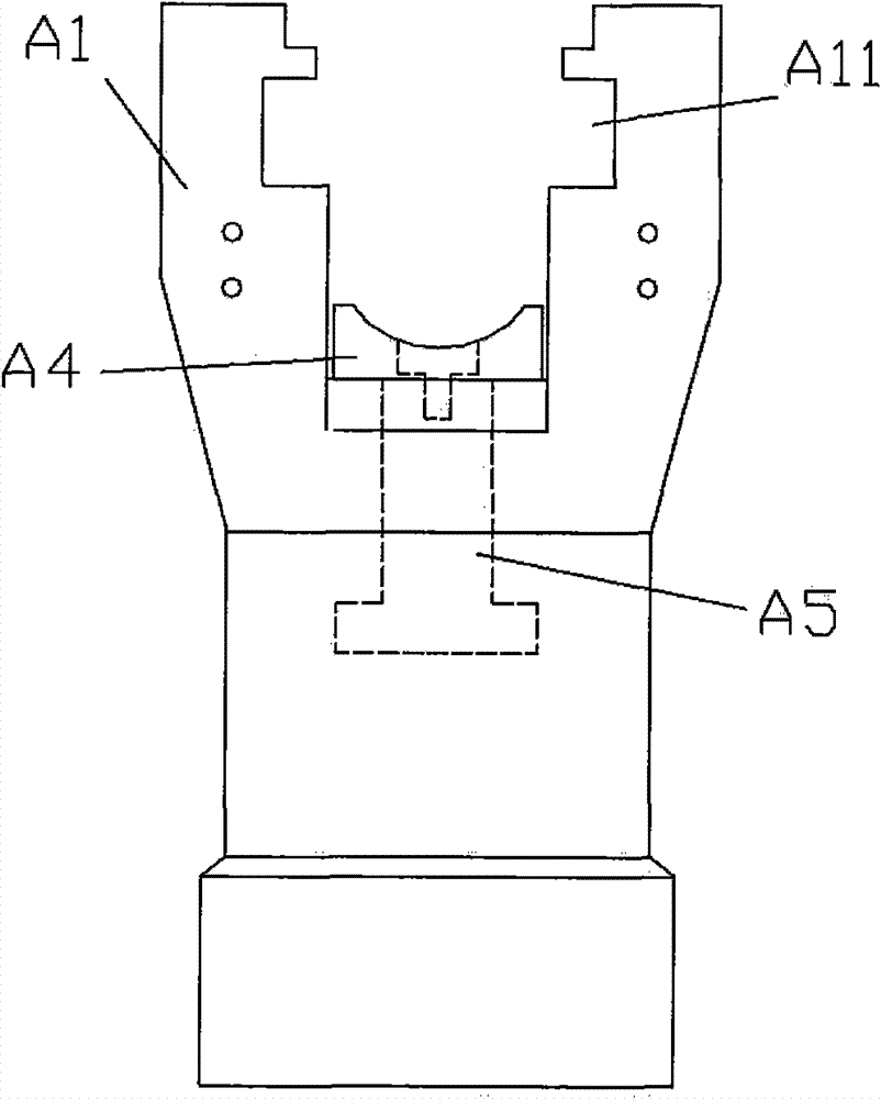
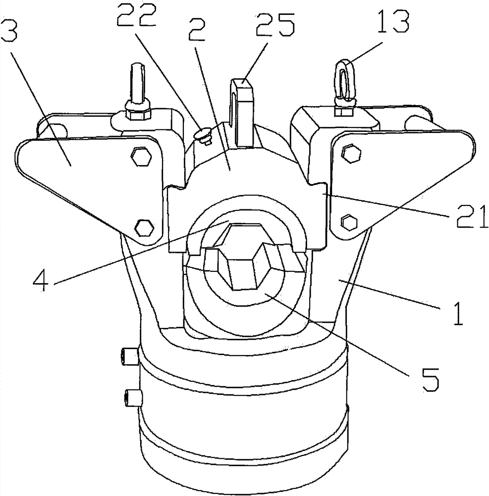
[0035] Examples, see Figure 3 to Figure 10 Shown: a split hydraulic pliers, including caliper body 1, pliers upper cover 2, handle 3, upper mold 4, lower mold 5 and piston 6, the piston is installed on the caliper body 1, and the caliper body 1 is fixedly connected with The handle 3 and the pliers body 1 are formed with a guide groove 11, and the corresponding pliers upper cover 2 is formed with a guide post 21, and the guide post 21 is inserted into the guide groove 11, and the pliers upper cover 2 is formed with a pliers upper cover positioning hole 23 , the positioning spring pin 22 of the upper mold and the upper cover of the clamp is installed;

[0036] The pliers body 1 is equipped with a pliers upper cover and a pliers body positioning spring pin 12, and the pliers upper cover and pliers body positioning...


PUM


Abstract

The invention discloses a split hydraulic clamp. A clamp upper cover and a clamp positioning spring pin are inserted into a clamp upper cover positioning hole, an upper die and clamp upper cover positioning hole is formed on an upper die, an upper die and clamp upper cover positioning spring pin is inserted into the upper die and clamp upper cover positioning hole, the upper die is inserted into the clamp upper cover, and an upper die pressing step butts against a clamp upper cover support step; a piston anti-rotation bulge is formed on a clamp body and is clamped in a piston anti-rotation groove; a lower die positioning pin presses a compression spring and is arranged in a lower die positioning pin installation hole, a notch is formed on the lower die positioning pin, and a handle extends into the notch; and a piston and lower die positioning hole and a lower die step are formed on a lower die, a piston pressing step is formed on the upper part of a lower die inserting groove, and the lower die step butts and presses against the lower part of the piston pressing step. The split hydraulic clamp has a simple structure, light weight and high bearing capacity and is low in production cost and easy to operate.

Description

technical field [0001] The invention relates to the technical field of hydraulic pliers, in particular to a kind of intermediate connecting pipe, tension clamp and equipment clamp suitable for overhead steel-cored aluminum stranded wire and steel stranded wire, and for crimping copper-aluminum with large cross-section Hydraulic pliers for cables. Background technique [0002] like figure 1 , 2 As shown, the existing BYO-300T split hydraulic tongs are composed of a caliper body A1, a tongs upper cover A2, a piston A5, an upper mold bracket A3, a lower mold bracket A4, an upper mold and a lower mold, and it has the following deficiencies: [0003] 1. A square guide post A21 is formed on the upper cover A2 of the pliers, and the square guide post A21 is inserted into the linear square guide groove A11 on the pliers body A1, so that when crimping, the square guide post A21 and the square guide groove A11 are about The shaking gap is large, causing large crimping errors. Dur...

Claims


Application Information

Patent Timeline
Patent Type & Authority Patents(China)
IPC IPC(8): H01R43/048B25B27/00
Inventor 吴书占
Owner 吴书占
Why Eureka
Try Eureka