Electromagnetic braking and controlling system of wind power generator
A wind turbine and control system technology, applied in the control system, control generator, electric brake/clutch, etc., can solve the problems of complex structure, damaged wind turbine, and low service life, so as to simplify the mechanical structure and prolong the service life Life and the effect of reducing the failure rate
- Summary
- Abstract
- Description
- Claims
- Application Information
AI Technical Summary
Problems solved by technology
Method used
Image
Examples
specific Embodiment 1
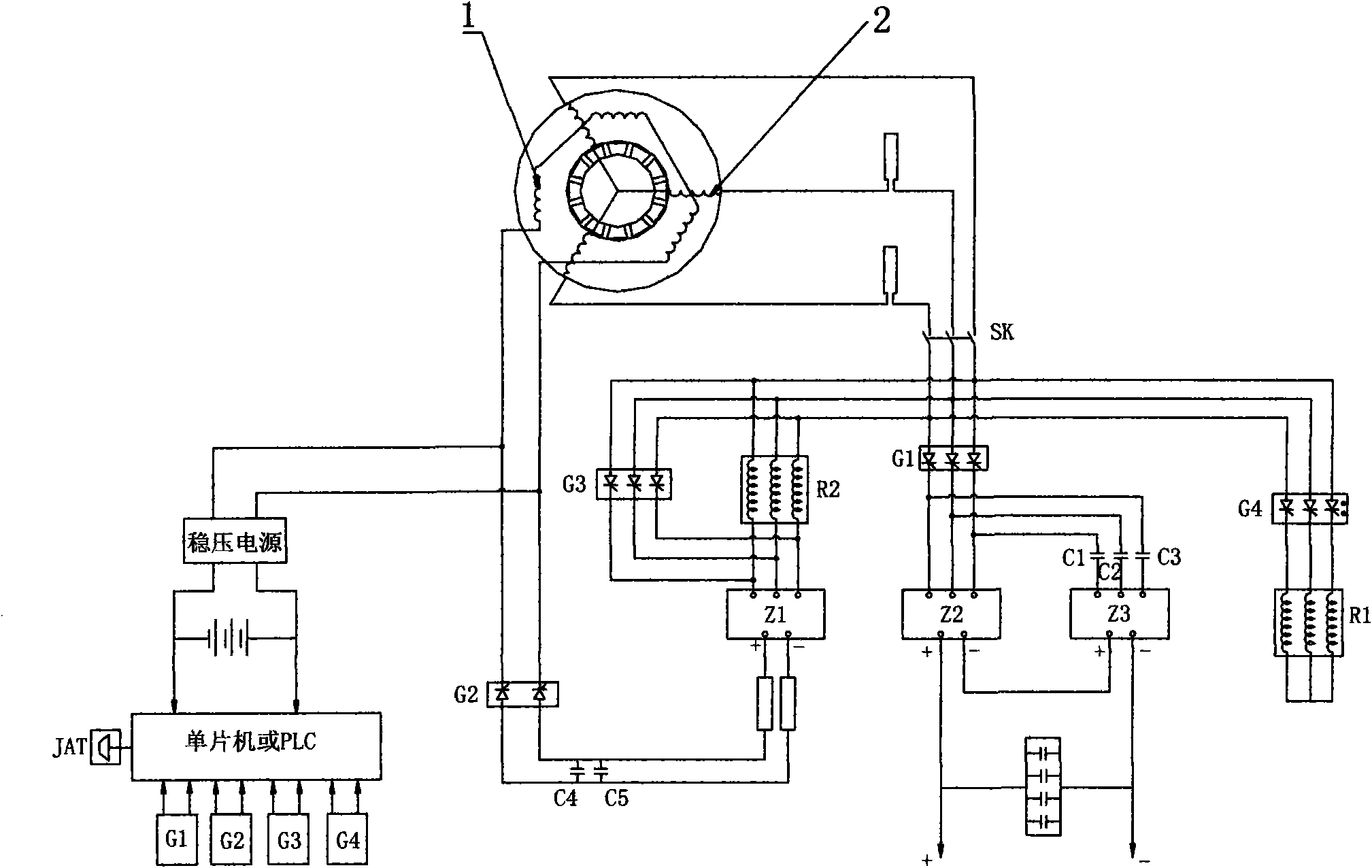
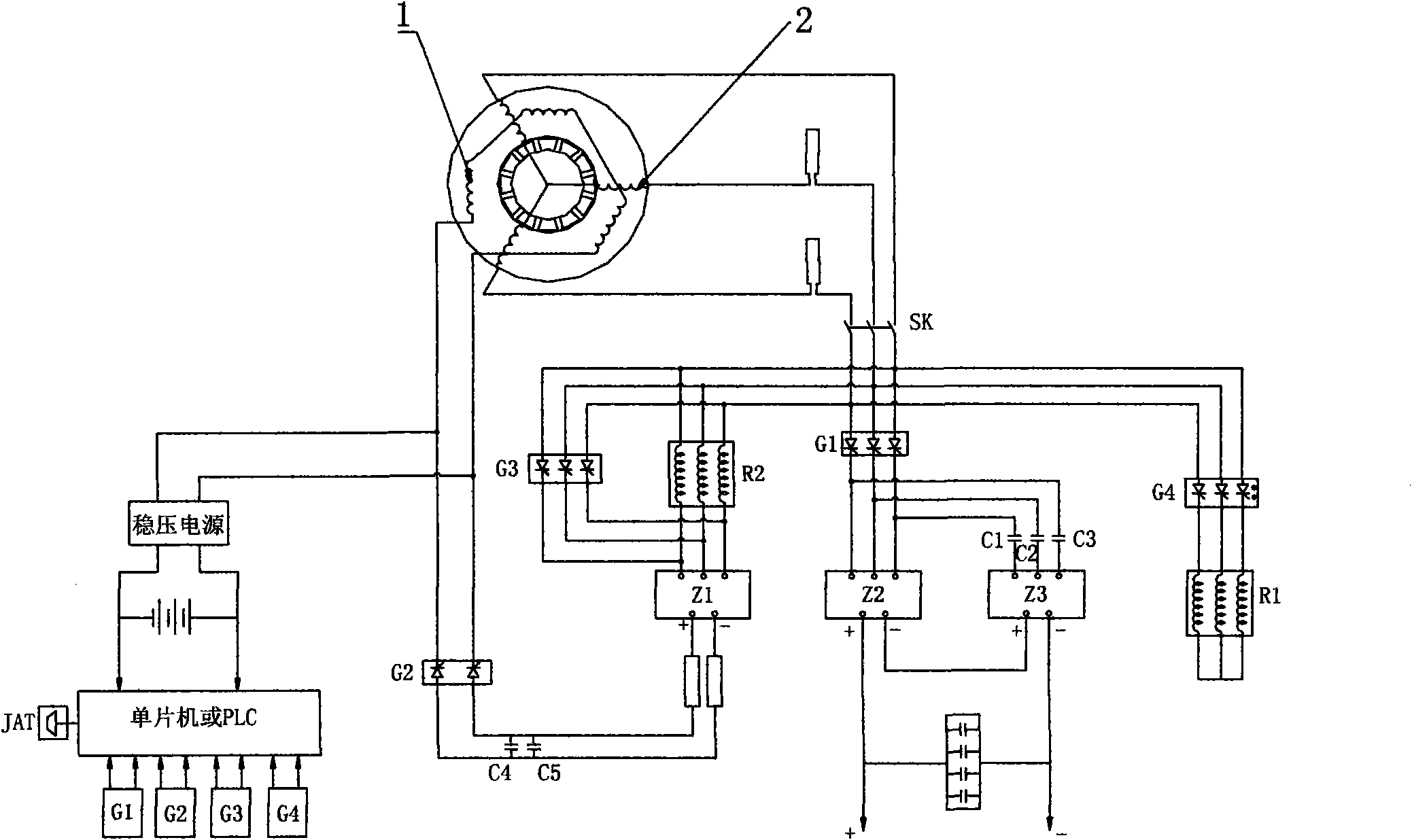
[0022] Specific embodiment 1: a wind-driven generator electromagnetic braking and control system, including a wind-driven generator and a control system connected to the winding of the wind-driven generator, the stator slot of the wind-driven generator is wound with a generator winding 2 and The braking winding 1, the generating winding 2 and the braking winding 1 are separated by an insulator; the output of the Y-connected generating winding 2 passes through the relay G1 and the rectifier bridges Z2 and Z3 to output direct current through the DC output terminal, and the generating winding The output of 2 is connected to the brake winding 1 after passing through the braking resistor R2, the rectifier bridge Z1 and the relay G2, and the two ends of the braking resistor R2 are connected with the relay G3, and the relays G1, G2, G3, and G4 are respectively connected to the The control system is connected and controlled by it. The output of the generating winding 2 is connected to...
specific Embodiment 2
[0026] Specific embodiment 2: a wind-driven generator electromagnetic braking and control system, including a wind-driven generator and a control system connected to the winding of the wind-driven generator, the stator slot of the wind-driven generator is wound with a generator winding 2 and The braking winding 1, the generating winding 2 and the braking winding 1 are separated by an insulator; the output of the Y-connected generating winding 2 passes through the relay G1 and the rectifier bridges Z2 and Z3 to output direct current through the DC output terminal, and the generating winding The output of 2 is connected to the brake winding 1 after passing through the braking resistor R2, the rectifier bridge Z1 and the relay G2, and the two ends of the braking resistor R2 are connected with the relay G3, and the relays G1, G2, G3, and G4 are respectively connected to the The control system is connected and controlled by it. The output of the brake winding is connected to the DC...
specific Embodiment 3
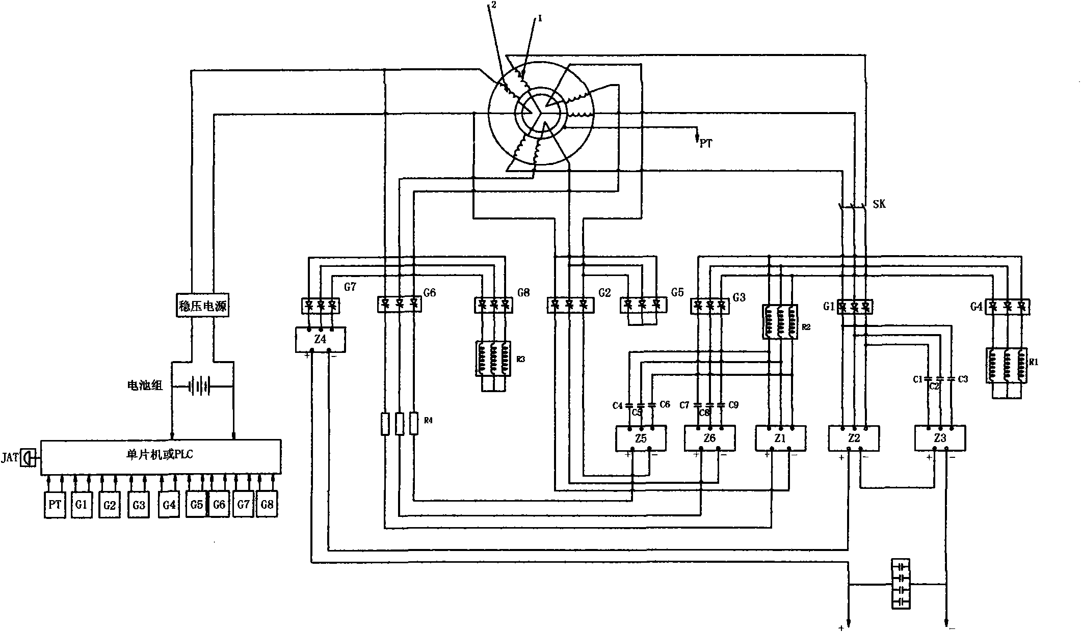
[0030]Specific embodiment 3: this specific embodiment is applicable to large-scale generating set, and the generating winding is a three-phase stator winding, and the braking winding is a three-phase six-wire braking winding. The load first transfers to the unloading resistor R1. After a delay, the generator speed decreases. The second step is to connect the braking resistor R2 and the current limiting resistor R4 in series to reduce the current impact. The braking winding 2 is connected, and the generator speed drops. At the lowest point, the generator winding 1 is directly connected to the brake winding 2 through G3. At this time, the generator stops completely. The brake winding 2 generates a current magnetic field, which forms a heteropolar magnetic field with the permanent magnet of the rotor, and the rotor is forcibly attracted to realize electromagnetic braking. It is also possible to provide one or more braking systems, one of which comprises a braking winding and an f...
PUM
 Abstract
Description
Claims
Application Information
 - R&D
- Intellectual Property
- Life Sciences
- Materials
- Tech Scout
- Unparalleled Data Quality
- Higher Quality Content
- 60% Fewer Hallucinations
Browse by: Latest US Patents, China's latest patents, Technical Efficacy Thesaurus, Application Domain, Technology Topic, Popular Technical Reports.
© 2025 PatSnap. All rights reserved.Legal|Privacy policy|Modern Slavery Act Transparency Statement|Sitemap|About US| Contact US: help@patsnap.com


